Telescopic cleaning valve

A cleaning valve, telescopic technology, applied in the field of cleaning equipment, can solve problems such as inconvenience, and achieve the effect of avoiding damage or pollution, no hygienic dead angle, and ensuring hygienic dead angle

Inactive Publication Date: 2011-10-26
浙江奥米科技有限公司
View PDF6 Cites 9 Cited by
  • Summary
  • Abstract
  • Description
  • Claims
  • Application Information

AI Technical Summary

Problems solved by technology

However, when the inner wall of the pipe or tank is too deep, the cleaning valve cannot freely expand and contract to clean the dirt at these positions, which is very inconvenient

Method used


Image

  • Telescopic cleaning valve
  • Telescopic cleaning valve

Examples


Embodiment Construction

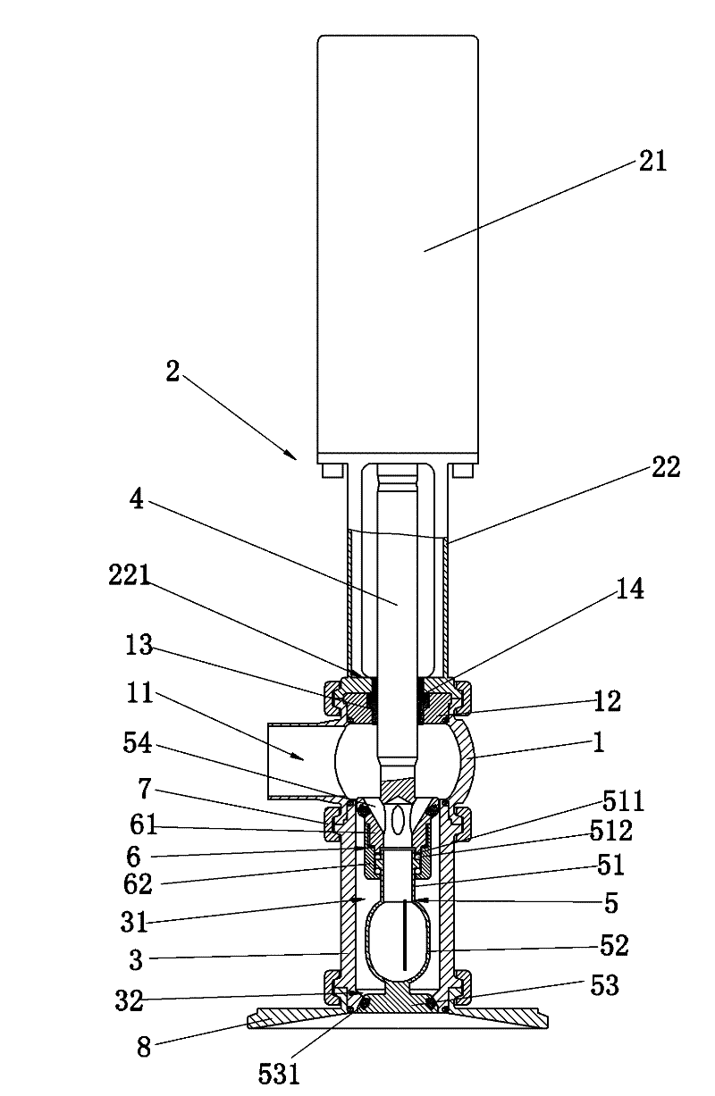
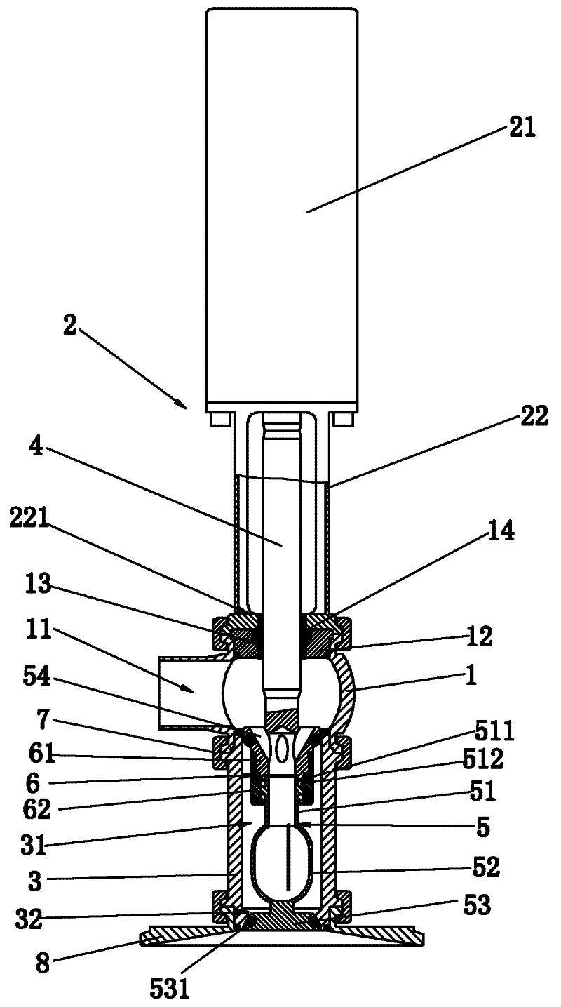
[0017] like figure 1 As shown, the embodiment of the present invention is specifically a telescopic cleaning valve, which includes a valve body 1 and a cleaning ball 5 arranged in the valve body 1. One side of the valve body 1 is provided with a cleaning liquid inlet 11, and the top of the valve body 1 An actuator 2 is provided, and the actuator 2 includes an execution system 21 and a bracket 22. The bracket 22 is set in cooperation with the valve body 1, and the joint is sealed. A valve stem 4 is arranged above the cleaning ball 5, and one end of the valve stem 4 is connected to the cleaning ball 5. Fixed, the cleaning ball 5 can rotate relative to the valve stem 4, the other end of the valve stem 4 extends through the bracket 22 and is fixed on the actuator 2, the valve stem 4 can do telescopic movement under the drive of the actuator 2, the bottom of the valve body 1 A cavity 31 is provided for placing the cleaning ball 5 . A boss 221 is provided below the bracket 22, a pr...


PUM


Abstract

The invention discloses a telescopic cleaning valve. The valve comprises a valve body and a cleaning ball in the valve body, wherein a cleaning solution inlet is arranged on one side of the valve body; an actuator is arranged above the valve body, and comprises an actuation system and a bracket; the bracket is matched with the valve body, and the matching position is sealed; a valve rod is arranged above the cleaning ball; the cleaning ball is fixed at one end of the valve rod, and can rotate relative to the valve rod; the other end of the valve rod extends and passes through the bracket, and is fixed on the actuator; the valve rod can make telescopic motion under driving of the actuator; and a cavity is arranged under the valve body for placement of the cleaning ball. The telescopic cleaning valve can be flexed freely, the cleaning ball is retracted into the cavity under the action of the valve rod after cleaning is completed, and the cleaning ball is protected from damage or pollution; furthermore, the cleaning ball can be pushed out by the valve rod under driving the actuator in cleaning, and rotates under the action of pressure of the cleaning solution to steadily clean cleaned equipment, so that no sanitary blind angle exists.

Description

technical field [0001] The invention relates to a cleaning device for cleaning objects, in particular to a telescopic cleaning valve. Background technique [0002] Frequently used tanks and pipelines such as various conveying pipelines, geothermal pipelines and chemical pipelines need to be cleaned frequently to ensure the smooth flow of the above-mentioned pipelines and avoid blockage. The traditional cleaning method is to put the pipeline or tank in the cleaning solution, so that the dirt attached to the inner wall of the pipeline or tank will automatically fall off and dissolve in the chemical cleaning agent, so as to achieve the purpose of cleaning the pipeline. After cleaning, discharge the cleaning liquid in the pipeline out of the pipeline or tank. This traditional cleaning method is more polluting, and requires a long cleaning time, high cleaning cost and poor cleaning effect on pipelines or tanks. [0003] Currently, another method for cleaning pipes or tanks on t...

Claims


Application Information

Patent Timeline
Patent Type & Authority Applications(China)
IPC IPC(8): B08B9/027B08B9/087
Inventor 唐龙
Owner 浙江奥米科技有限公司
Why Eureka
Try Eureka