Sound suppressing device for tire tread

A technology for tires and treads, applied in the direction of tire tread/tread pattern, tire parts, transportation and packaging, etc., can solve problems such as interrupting the flow of liquid in grooves

Active Publication Date: 2011-10-26
OCIETE DE TECH MICHELIN
View PDF3 Cites 10 Cited by
  • Summary
  • Abstract
  • Description
  • Claims
  • Application Information

AI Technical Summary

Problems solved by technology

[0004] While the device is effective, these units can still disrupt flu

Method used


Image

  • Sound suppressing device for tire tread
  • Sound suppressing device for tire tread
  • Sound suppressing device for tire tread

Examples


Embodiment Construction

[0024] In order to facilitate understanding of the drawings and the related description, the same reference numerals are used in the figures to refer to structural or functional elements that are the same regardless of the variation involved.

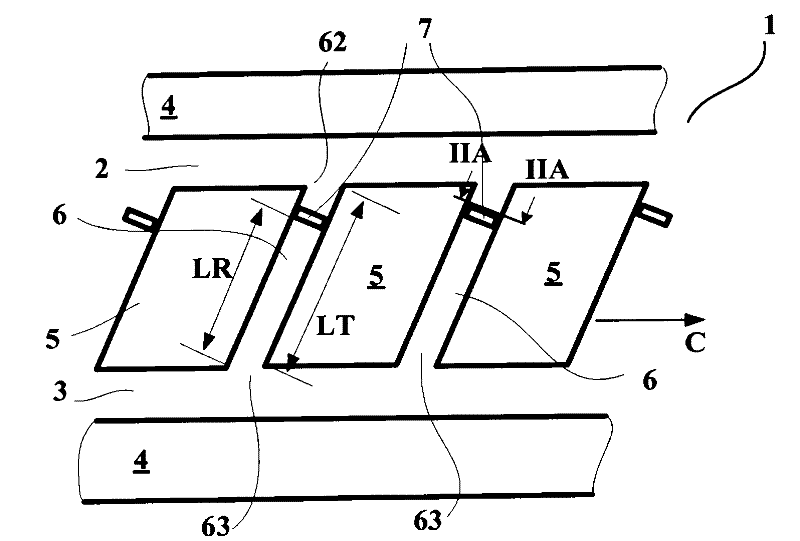
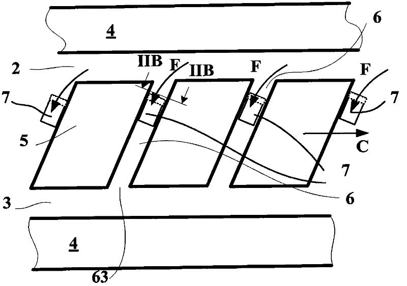
[0025] Figure 1A and 1B A view showing the running surface of a part of a tread 1 according to a first variant of the invention, which is designed to be fitted to a tire for passenger cars. The tire size is 255 / 40 R 19. These views show two circumferential grooves 2 , 3 each delimited by circumferentially continuous ribs 4 and a row of blocks 5 . The blocks 5 are separated from each other in the circumferential direction by inclined lug grooves 6, that is to say the lug grooves 6 form a non-zero angle with the circumferential direction indicated by the direction C in the drawing.

[0026] The circumferential grooves 2, 3 have an average width of 10 mm and a depth of 8 mm. The transverse grooves 6 have an average width of 3 mm and a ...


PUM


Abstract

The present invention relates to a tire having a tire tread (1) that includes: at least two grooves (2, 3) in a general circumferential direction; a plurality of transverse grooves (6), each transverse groove leading into two circumferential grooves via openings (62, 63), the circumferential and transverse grooves having transverse sections suitable for enabling liquid on the road to flow while the wheels are turning; and a plurality of closing devices (7) located in said grooves, each closing device at least partially closing the transverse section of a groove, each closing device (7) defining, with the end (62, 63) of the transverse groove end (6), a groove length LR from one half to three quarters of the length of an in contact circumferential groove and measured under nominal conditions for load and pressure. Said tire is characterized in that each closing device (7) is designed to bend and open the groove section in which the device is placed, being moved by a liquid flow so as to enable the flow of said liquid when the wheels are turning on a road covered with water.

Description

technical field [0001] The present invention relates to tire treads, and more particularly, to the siping of these treads. Background technique [0002] In order to achieve the essential road handling and grip properties, it is known in practice to provide a tread for a tire provided with a plurality of generally circumferentially (or longitudinally) oriented grooves (grooves). The grooves are defined by opposing walls separated from each other by a distance of at least greater than 2 mm, which walls may be flat or corrugated or zigzag. These side walls are connected by a bottom wall. When driving, the grooves are closed by contact with the road surface and the ends are formed to allow fluid to flow within the grooves. [0003] It has been found that at certain driving speeds, the air flow in the circumferential grooves can produce resonant noise that increases the perceived sound level. It is known in practice to provide gates in these grooves, which reduce the length of...

Claims


Application Information

Patent Timeline
IPC IPC(8): B60C11/13B60C19/00
CPCB60C11/13B60C19/00B60C19/002B60C2011/1361B60C11/1369
Inventor N·多特雷
Owner OCIETE DE TECH MICHELIN
Why Eureka
Try Eureka