Vibration generating device

A technology of vibration generation and vibrating parts, applied in electromechanical devices, fluids using vibration, electrical components, etc., can solve problems such as reducing the overall structural limit, reducing the size of the vibrating body, and reducing the size of the spring

Inactive Publication Date: 2011-11-09
ALPS ALPINE CO LTD
View PDF5 Cites 16 Cited by
  • Summary
  • Abstract
  • Description
  • Claims
  • Application Information

AI Technical Summary

Problems solved by technology

[0007] However, the vibrating body of the conventional example described in Patent Document 1 is formed by surrounding the entire outer circumference of a cylindrical magnet moving in the axial direction with a cylindrical coil. There is a limit on the size of the thickness direction)
In addition, since the spring supporting the vibration of the vibrating body is formed of a coil spring, there is also a limit to reducing the size of the spring in the diameter direction (corresponding to the thickness direction).
Therefore, in the conventional examples described above, there is a limit to reducing the size of the overall structure in the thickness direction.

Method used


Image

  • Vibration generating device
  • Vibration generating device
  • Vibration generating device

Examples


Embodiment Construction

[0036] Hereinafter, embodiments of the present invention will be described in detail based on the drawings.

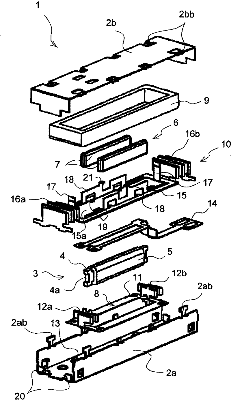
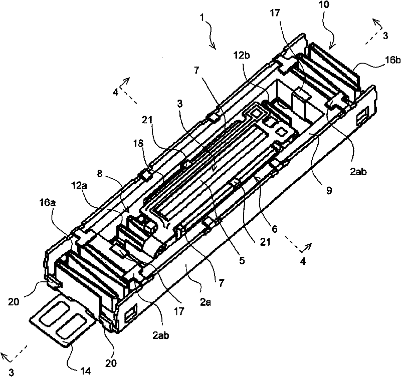
[0037] Figure 1 to Figure 5 An embodiment of the present invention is shown.

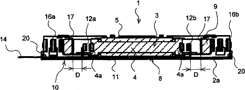
[0038] The vibration generating device 1 of the present embodiment is installed in a flat hollow rectangular parallelepiped frame 2. figure 1 Each of the components shown is formed to generate large vibrations of two frequencies.

[0039] In the present embodiment, the casing 2 is provided with: a first vibrator 3 wound with a coil 5 around the outer peripheral surface of the iron core 4, and vibrating by a magnetic field generated by the coil 5; A pair of magnets 7, 7 with the same poles facing each other on both sides of a vibrating element 3; The two ends) are supported to vibrate freely; the second vibrator 9, which is connected to the magnetic field forming part 6, is subjected to the reaction force of the interaction between the magnetic field generated by the coil 5 and the magnet...


PUM


Abstract

The invention provides a vibration generating device of which the entire configuration may have a small size in a thickness direction, which can obtain a large vibration, and which can give vibrations with a plurality of large frequencies. The vibration generating device includes a coil (5) wound around an outer peripheral surface of a core (4), a vibrator (3) vibrating due to a magnetic field generated by the coil (5), a magnetic field forming unit having a pair of magnets (7) oppositely disposed at both surfaces of the vibrator (3) so that the same polarities face each other or one magnet (7) disposed at one side surface of the vibrator (3), and an elastic support member (8) for supporting the vibrator (3) so that the vibrator (3) is capable of freely vibrating, wherein a vibrating direction of the vibrator (3) is set to be parallel to a fixed surface of the device, by means of a magnetic flux generated by the magnetic field forming unit (6).

Description

technical field [0001] The present invention relates to a vibration generating device, in particular to a vibration generating device suitable for being mounted on a portable device. Background technique [0002] Generally, a vibration generating device is built into portable devices such as mobile phones and controllers of game machines in order to obtain various usability. [0003] In such a portable device, the overall housing tends to be thinner, and the demand for thinner built-in components is also increasing. [0004] For the vibration generating device, it is also required to reduce the thickness. However, for the structure that sets the vibration direction along the thickness direction, if the thickness is reduced, the vibration space inside the frame will also become smaller, so there is a problem that it cannot be set larger. Vibration problem. [0005] Therefore, it has been proposed to set the vibration direction not in the thickness direction of the housing b...

Claims


Application Information

Patent Timeline
Patent Type & Authority Applications(China)
IPC IPC(8): B06B1/04
CPCH02K33/16H02K33/00H02K33/18B06B1/045B06B1/04B06B1/14
Inventor 和宇庆朝邦
Owner ALPS ALPINE CO LTD
Why Eureka
Try Eureka