
Electronic apparatus

A technology of electronic devices and vibrating bodies, which is applied in the fields of electrical digital data processing, instruments, teaching aids, etc., and can solve problems such as unstable supporting touch panels.

Inactive Publication Date: 2006-08-23
NEC INFRONTIA CORP
View PDF1 Cites 16 Cited by
  • Summary
  • Abstract
  • Description
  • Claims
  • Application Information

AI Technical Summary

Problems solved by technology

Accordingly, the conventional electronic device has a problem in that the supporting member unstablely supports the touch panel

Method used


Image

  • Electronic apparatus
  • Electronic apparatus
  • Electronic apparatus

Examples


Embodiment Construction

[0031] Reference Figure 1-3 , The electronic device according to the first embodiment of the present invention will be explained.

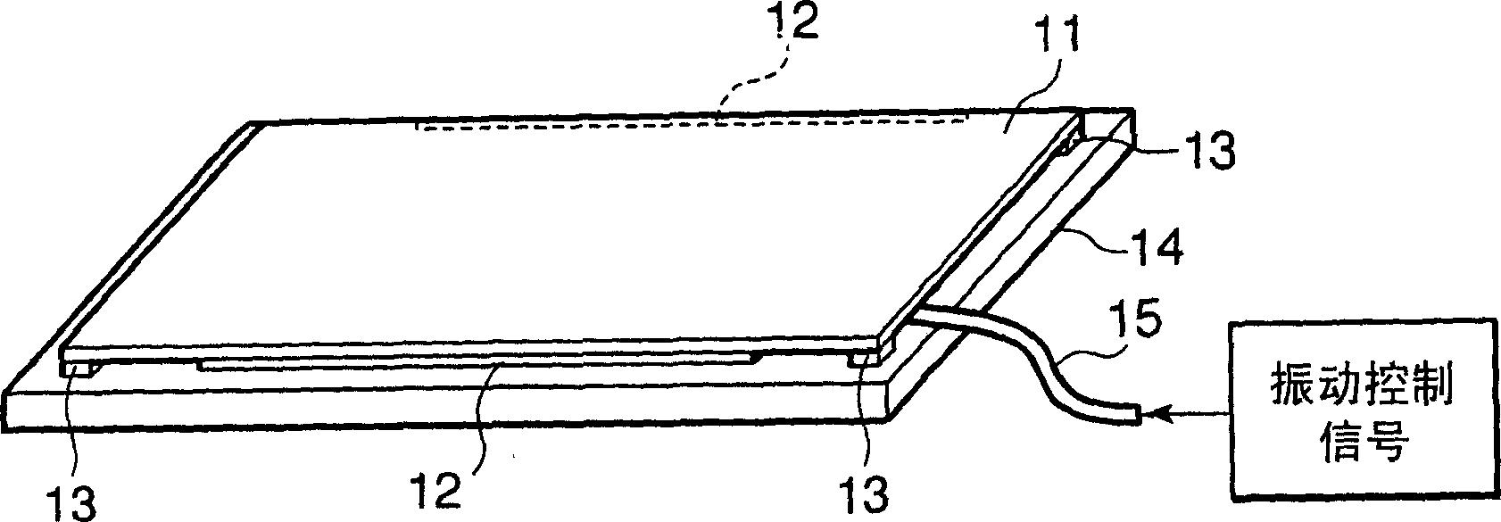
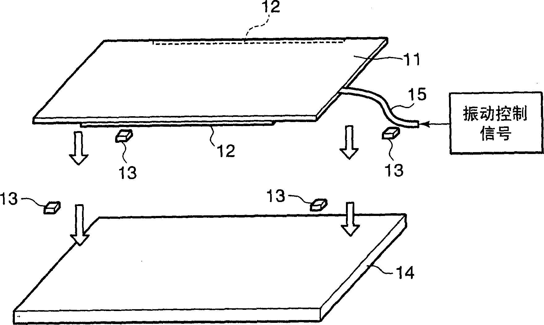
[0032] figure 1 Is a perspective view of the electronic device (or panel assembly) of the first embodiment and figure 2 Is its exploded perspective view.

[0033] The electronic device includes a rectangular touch panel (or flat vibrating body) 11 having a glass or resin substrate on the rear surface. On the rear surface of the touch panel 11, a pair of vibrating elements 12 are along the upper (or figure 2 Behind) and below (or figure 2 The front side) is fixed. The rear surface of the touch panel 11 corresponds to the exposed surface of the glass or resin substrate. In addition, on the rear surface of the touch panel 11, four fixing pads 13 are fixed on the four corners (near) of the touch panel 11. The fixed frame 14 has a frame or a rectangular shape whose length and width are almost equal to or slightly larger than the touch panel 11 to sup...


PUM


Abstract

In an electronic apparatus having a touch panel, four fixing cushions are fixed at four corners of a rear surface of the touch panel. The fixing cushions are further fixed to a fixing frame to support the touch panel against to the fixing frame. Pair of vibrating elements are fixed to the rear surface of the touch panel along edges, which are parallel to each other, of the touch panel. The vibrating elements elastically bend the touch panel to cause flexural vibration to the touch panel. The fixing cushions have softness to allow the touch panel to vibrate and hardness to serve as fulcrums of the flexural vibration of the touch panel.

Description

[0001] This application claims the priority of the previous Japanese JP2005-037765 application, and the content of the disclosure is hereby incorporated for reference. Technical field [0002] The present invention relates to an electronic device, and in particular, to an improvement of an electronic device configured such that a flat vibrating body (for example, a touch panel) is vibrated by a vibrating element. Background technique [0003] The touch panel is known as an input device of an electronic device. One type of touch panel provides a vibration function to give the operator a feeling of operation. [0004] The touch panel with vibration function vibrates when its surface is pressed by the operator's fingers, the stylus held by the operator, or the like. The vibration of the touch panel is transmitted to the operator through his / her fingers or the like. In this way, the operator perceives whether the input operation performed by the operator is accepted by the electronic ...

Claims


Application Information

Patent Timeline
Patent Type & Authority Applications(China)
IPC IPC(8): G06F3/01G06F1/16
CPCG06F3/041G06F3/016G09B21/003G06F3/0412
Inventor 西村秀树山下俊一
Owner NEC INFRONTIA CORP
Learn More