Vibration-proof mount

a technology of vibration-proof mounts and mounting brackets, which is applied in the direction of shock absorbers, machine supports, jet propulsion mountings, etc., can solve the problems of poor ability to absorb small vibrations, inability to form perforations in the vibration-proof member, and ineffective absorption of large vibrations

Inactive Publication Date: 2000-09-12
HONDA MOTOR CO LTD
View PDF5 Cites 15 Cited by
  • Summary
  • Abstract
  • Description
  • Claims
  • Application Information

AI Technical Summary

Benefits of technology

According to this arrangement, only the vibration-proof member elastically deforms until the amount of relative displacement, in the diametrical direction, between the inner cylinder and the outer cylinder reaches the predetermined value. Once the amount of relative displacement has exceeded the predetermined value, the stopper member, in addition to the vibration-proof member, also elastically deforms. Therefore, in a region in which the amount of relative displacement is below the predetermined value, the spring constant of the mount becomes small, whereby small vibrations can be efficiently absorbed. In a region in which the amount of relative displacement is above the predetermined value, the spring constant of the mount becomes large, whereby large vibrations can also be effectively absorbed.
The vibration-proof member tends to expand in the axial direction due to compression in the diametrical direction. If this expansion is restricted, the spring constant of the vibration-proof member increases, whereby the ability to absorb the small vibrations becomes poor. Therefore, it is preferable to secure a first axial clearance between the stopper member and that portion of the vibration-proof member which connects the inner cylinder and the outer cylinder. In this arrangement, while the amount of relative displacement, in the axial direction, between the inner cylinder and the outer cylinder is small, only the vibration-proof member elastically deforms in the axial direction. Once the amount of this relative displacement has exceeded the width of the above-described clearance, the vibration-proof member comes into abutment with the stopper member, whereby the stopper member also elastically deforms in the axial direction. Therefore, there can be obtained a function of switching the spring constant in the axial direction of the vibration-proof mount, with the result that the capability of absorbing the vibrations in the axial direction can be improved.
Further, if an arrangement is made that the stopper member further comprises a flange portion which abuts an axial end of the outer cylinder and that the flange is formed such that a second axial clearance is secured between the flange and a bracket which pivotally mounts the inner cylinder, the flange portion advantageously functions as a stopper to prevent the outer cylinder from excessively deforming, relative to the inner cylinder, in the axial direction of the vibration-proof mount. In case the first axial clearance is secured between the stopper member and that portion of the vibration-proof member which connects the inner cylinder and the outer cylinder, the width of the second axial clearance is made larger than the axial width of the first clearance. According to this arrangement, before the relative displacement, in the axial direction, of the outer cylinder relative to the inner cylinder is restricted by the abutment of the flange portion with the bracket, the vibration-proof member comes into abutment with the stopper member. As a result, the function of switching the spring constants is not impaired.

Problems solved by technology

Once the perforations have been crushed, the spring constant of the vibration-proof mount becomes large, with the result that large vibrations can also be effectively absorbed.
However, in the case of the vibration-proof mount for an electric motor which serves as the driving source of an electric vehicle, the perforations cannot be formed in the vibration-proof member in view of the frequencies of the vibrations which are generated in the electric motor.
If this expansion is restricted, the spring constant of the vibration-proof member increases, whereby the ability to absorb the small vibrations becomes poor.

Method used


Image

  • Vibration-proof mount
  • Vibration-proof mount
  • Vibration-proof mount

Examples


Embodiment Construction

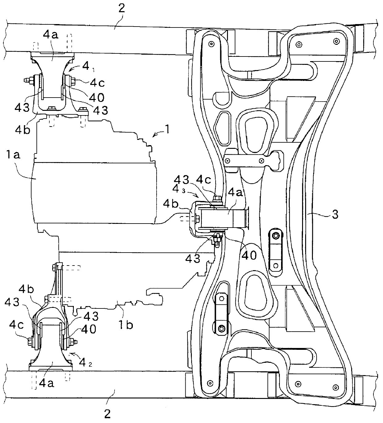
FIG. 1 shows that portion of an electric vehicle in which a driving source 1 is disposed. The driving source 1 is constituted by an electric motor 1a and a reduction gear 1b which is attached to one end of the electric motor 1a. The driving source 1 is supported on a vehicle body by means of three vibration-proof mounts 4.sub.1, 4.sub.2, 4.sub.3 which are respectively disposed on side frames 2, 2 on right and left sides of the vehicle body and on a cross beam 3 which is provided to bridge across both the side frames 2, 2.

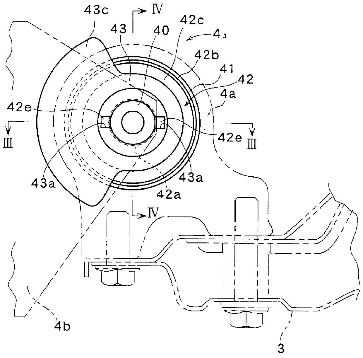
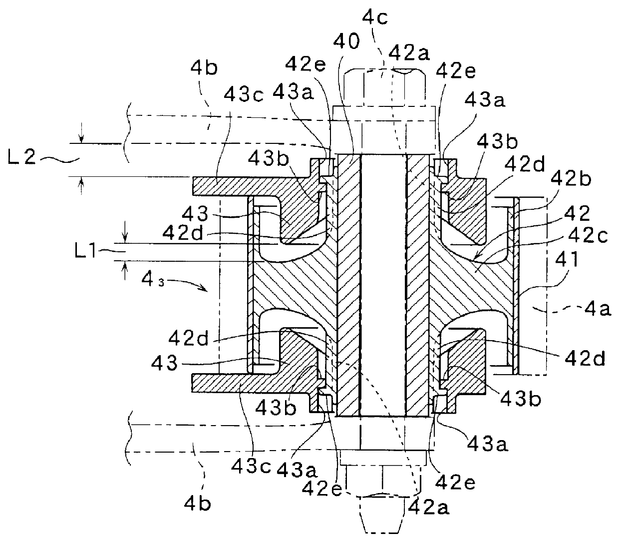
As shown in FIGS. 2 through 4, each of the vibration-proof mounts 4.sub.1, 4.sub.2, 4.sub.3 is provided with an inner cylinder 40, an outer cylinder 41, and a vibration-proof member 42 which is made of an elastic material such as rubber, or the like, and which connects the inner and the outer cylinders 40, 41. The outer cylinder 41 is fitted by force into a bracket 4a which is on the side of the vehicle body, and the inner cylinder 40 is pivotally mounted on a fork-...


PUM


Abstract

A clearance which is not filled with a vibration-proof member is provided between an inner cylinder and an outer cylinder. A stopper member which is made of an elastic member is disposed in this clearance. When the amount of relative displacement, in the diametrical direction, of the inner and outer cylinders has exceeded a predetermined value, the stopper member is elastically deformed. A clearance in the axial direction is secured between the stopper member and that portion of the vibration-proof member which connects the inner cylinder and the outer cylinder. In this manner, a function of switching the spring constant can also be obtained in a solid type of mount without a perforation in the vibration-proof member which is made of an elastic member to connect the inner cylinder and the outer cylinder.

Description

1. Field of the InventionThe present invention relates to a vibration-proof mount (or mounting, or mounting element) for use in supporting a driving source of a vehicle on a vehicle body.2. Description of the Related ArtConventionally, this kind of vibration-proof mount is made up of an inner cylinder, an outer cylinder and a vibration-proof member such as rubber, or the like, which connects the inner cylinder and the outer cylinder. One of the inner cylinder and the outer cylinder is connected to the vehicle body and the other thereof is connected to the driving source.In this kind of vibration-proof mount, there is also known one in which axial perforations are formed in the vibration-proof member. In this conventional vibration-proof mount, the spring constant of the vibration-proof mount becomes small until the perforation is crushed, with the result that the fine or small vibrations can be efficiently absorbed. Once the perforations have been crushed, the spring constant of the...

Claims


Application Information

Patent Timeline
Patent Type & Authority Patents(United States)
IPC IPC(8): B60K5/12F16F1/387F16F1/38F16F15/08
CPCB60K5/1216F16F1/387
Inventor MIYAHARA, TETSUYA
Owner HONDA MOTOR CO LTD
Why Eureka
Try Eureka