Mold and injection molding apparatus

A mold and molding cavity technology, which is applied in the field of injection molding machines, can solve problems such as prolonging the time for product sample delivery and mass production, reducing production yield, and air bubbles in semi-finished products

Inactive Publication Date: 2011-11-09
HONG FU JIN PRECISION IND (SHENZHEN) CO LTD +1
View PDF3 Cites 0 Cited by
  • Summary
  • Abstract
  • Description
  • Claims
  • Application Information

AI Technical Summary

Problems solved by technology

If the air in the runner and molding cavity is not discharged cleanly, it will cause air bubbles in the semi-finished product, which will reduce the production yield, thus prolonging the time for sample delivery and mass production of subsequent products

Method used


Image

  • Mold and injection molding apparatus
  • Mold and injection molding apparatus
  • Mold and injection molding apparatus

Examples


Embodiment Construction

[0025] The present invention will be described in further detail below in conjunction with the accompanying drawings.

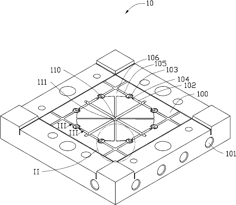
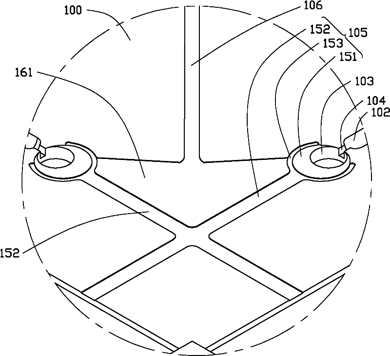
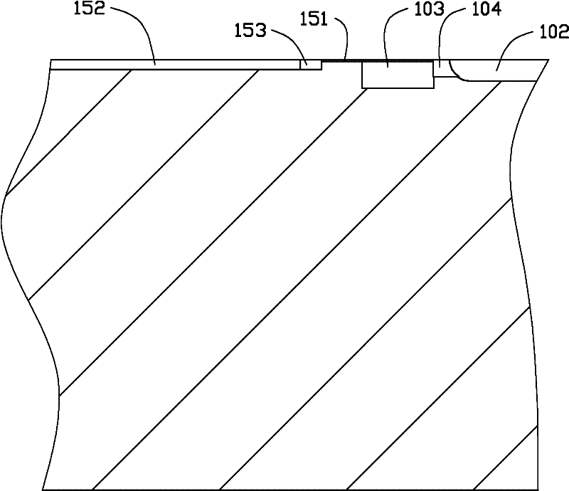
[0026] see figure 1 , A mold 10 provided by an embodiment of the present invention includes a parting surface 100 , a sprue 110 and a plurality of cooling channels 101 . The parting surface 100 is provided with 8 runners 102 (hereinafter referred to as runners 102 ), 8 molding cavities 103 , 8 gates 104 , 8 main exhaust slots 105 and 4 secondary exhaust slots 106 . For the convenience of description, only one of the above-mentioned components is used to illustrate the embodiment of the present invention. It can be understood that the present invention is not limited to the implementation of the above number of elements, and the specific number can be determined according to actual design and needs.

[0027] The cooling channel 101 is used for passing a cooling liquid (not shown in the figure) to cool the mold 10 . The branch channel 102 communicates with t...


PUM


Abstract

The invention relates to a mold. The mold comprises a parting face. The parting face is provided with flow channels, molding chambers communicated with the flow channels, and geats of the molding chambers. The parting face is further provided with main exhaust grooves. The main exhaust groove comprises an air inlet groove part and an air discharge groove part communicated with the air inlet groove part. The air inlet groove part is connected with the geat and surrounds the molding chamber. The air discharge groove part extends to an edge of the parting face. With the present invention, the mold is provided with the exhaust grooves through the parting face, the air in a molten molding material can be discharged when the molten molding material sequentially passes through the flow channels and the molding chambers, such that the half finished product does not have air bubbles, production yield is improved, so as to reduce feeding time and mass-production time of the follow-up sample. The invention further relates to an injection molding apparatus comprising the mold.

Description

technical field [0001] The invention relates to a mold and an injection molding machine including the mold. Background technique [0002] The molding die usually has a runner and a molding cavity communicated with the runner. In the injection molding process, the molten molding material squeezes the air out of the runner and molding cavity to fill the runner and molding cavity, and finally the molding material is cooled to become a semi-finished product. The semi-finished products are finally processed into finished products. If the air in the runner and molding cavity is not discharged cleanly, it will cause air bubbles in the semi-finished product, which will reduce the production yield, thus prolonging the time for sample delivery and mass production of subsequent products. Contents of the invention [0003] In view of this, it is necessary to provide a mold that can improve production yield and an injection molding machine including the mold. [0004] A mold include...

Claims


Application Information

Patent Timeline
Patent Type & Authority Applications(China)
IPC IPC(8): B29C45/26B29C45/63
Inventor 郭明龙
Owner HONG FU JIN PRECISION IND (SHENZHEN) CO LTD
Why Eureka
Try Eureka