Needle guiding sheet

A technology of a needle guide piece and a guide needle, which is applied in the field of needle guide pieces and can solve the problems of complex structure of the needle piece and the like

Active Publication Date: 2011-11-09
KARL MAYER STOLL R&D GMBH
View PDF5 Cites 3 Cited by
  • Summary
  • Abstract
  • Description
  • Claims
  • Application Information

AI Technical Summary

Problems solved by technology

[0003] Known selection sliders are complex
In addition, it was not possible before to prevent unintentional sinking of the drive foot of the needle if the needle is strongly loaded in the axial direction

Method used


Image

  • Needle guiding sheet
  • Needle guiding sheet
  • Needle guiding sheet

Examples


Embodiment Construction

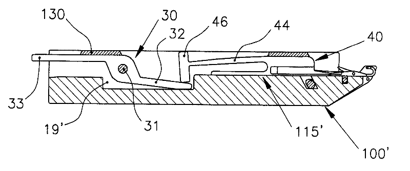
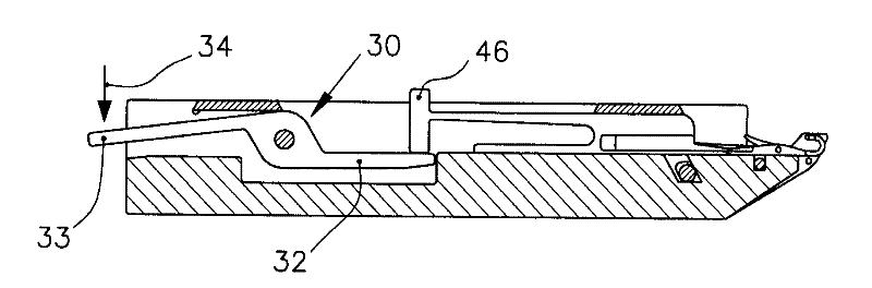
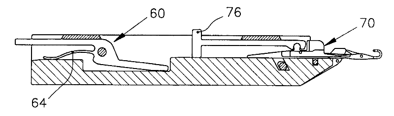
[0021] Figures 1a to 1d A section through a needle bed 100 is shown in each case in the region of the needle groove 110 in which a knitting needle 10 and a slider 11 are arranged. The knitting needle 10 together with its adjacent needles is protected by a cover rail 120 , and the slider 11 together with its adjacent slider is protected by a cover rail 130 against being lifted out of the needle groove 110 . The needle groove has a recess 19 in the needle base 115 .

[0022] exist Figure 1a There are both needles 10 and slider 11 in their inactive initial position. The slider 11 is moved backwards by means of a positioning foot 12 until the blocking positioning foot 12 enters its initial position on the cover rail partition 130 . The hooks 13 of the knitting needles 10 are located at the same position as the comb needles. In its rear area, the knitting needle 10 has a spring section 14 on the needle shaft 15, at its rear end a drive foot 16 for the knitting needle is arra...


PUM


Abstract

The invention relates to a needle guiding sheet, which is a needle guiding sheet (11) for knitting needle (10), wherein the needle guiding sheet (11) can make a transmission pin (16) of the knitting needle (10) and sinking into a needle bed be lifted to the needle bed, and a needle bottom (115) of the knitting needle (10) can be constructed, the needle bottom can be used to stop the transmission pin (16) of the knitting needle (10) from sinking into the needle bed.

Description

technical field [0001] The invention relates to a slider for the knitting needles of a knitting machine, wherein the needles are arranged in a needle groove of the needle bed, and a driving foot of the knitting needle which is sunk in the needle bed can be lifted with the slider onto the bed of needles. Background technique [0002] Such sliders for knitting needles of knitting machines, in particular flat knitting machines, are well known. For example, document DE 687 608 describes a selection slider with which a driving foot of a knitting needle which is sunk in the needle bed can be lifted above the needle bed so that it can be clamped by the cam of the knitting system Drive foot. The distance traveled by the drive foot through the cam determines what function the needle performs, that is to say whether it forms a loop, hooks and tucks, or remains in an inactive position. [0003] The known selection sliders are complex in structure. Furthermore, it has not previously...

Claims


Application Information

Patent Timeline
Patent Type & Authority Applications(China)
IPC IPC(8): D04B15/00D04B15/32
CPCD04B15/68
Inventor A.迪博尔德S.迈尔
Owner KARL MAYER STOLL R&D GMBH
Why Eureka
Try Eureka