Threading hook base of single-needle embroidering robot

A robot and threading technology, applied in embroidery machines, embroidery machine mechanisms, sewing equipment, etc., can solve problems such as manual threading and lead, and achieve the effect of improving work efficiency, saving manpower, and facilitating thread changing.

Inactive Publication Date: 2011-11-09
DALIAN DASEN NUMERICAL CONTROL CO LTD
View PDF10 Cites 1 Cited by
  • Summary
  • Abstract
  • Description
  • Claims
  • Application Information

AI Technical Summary

Problems solved by technology

[0003] In order to overcome the problem that traditional computerized embroidery machines need manual threading and threading, the present invention provides a single-needle embroidery robot threading hook base

Method used


Image

  • Threading hook base of single-needle embroidering robot
  • Threading hook base of single-needle embroidering robot

Examples


Embodiment Construction

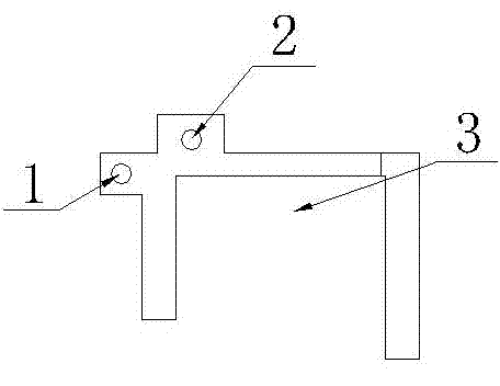
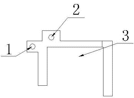
[0007] The single-needle embroidery robot threading hook base structure of the present invention is as follows: figure 1 As shown, the threading hook base is installed on the upper beam of the single-needle embroidery robot, and is used to install the threading hook, the thread introducing threading hook device and the base body of the threading hook fixing block. The threading hook base of the single-needle embroidery robot is made of metal material. The bottom of the threading hook base is a limit groove 3, and the threading hook base is provided with an air pipe installation hole 2 and a limit screw installation hole 1.

[0008] Traditional computerized embroidery machines do not have this part, and the upper thread is manually introduced into the pinhole. The threading hook of this embroidery robot is installed on the above-mentioned threading hook base, and the aerodynamic principle is used to realize the computer-controlled automatic threading and leading function of the...


PUM


Abstract

The invention discloses a threading hook base of a single-needle embroidering robot. A limit groove is arranged below the threading hook base; and an air tube mounting hole and a limit screw mounting hole are arranged on the threading hook base. The threading hook base of a single-needle embroidering robot is a device for supporting and mounting a threading hook as well as an indispensable component for realizing the automatic threading function under the computer control of an embroidering machine. By using the threading hook base to carry out automatic threading, the working efficiency is improved, the labor is saved, threads can be changed conveniently, and the functions of changing colors and threads without changing needles and the like can be achieved.

Description

technical field [0001] The invention relates to the field of embroidery machines, in particular to a threading hook base device of a computerized embroidery machine. Background technique [0002] With the development of computer and automatic control technology, computerized embroidery machines have replaced traditional manual mechanical embroidery machines and are being used more and more widely. In the process of embroidery, the traditional computerized embroidery machine adopts multi-needle embroidery, and changes colors by changing needles. There is no automatic threading device, and the function of automatic threading cannot be realized. The computer used for control cannot realize functions such as automatic imaging. There are great limitations in it, which affects the embroidery effect. Especially in the operation process, the upper line is manually introduced into the pinhole, which is inconvenient to operate, time-consuming and laborious, and the work efficiency is...

Claims


Application Information

Patent Timeline
Patent Type & Authority Applications(China)
IPC IPC(8): D05C11/00D05C11/16
Inventor 黄贤鸿许维亮丛凤龙
Owner DALIAN DASEN NUMERICAL CONTROL CO LTD
Why Eureka
Try Eureka