Supercharge Your Innovation With Domain-Expert AI Agents!

Driver torque request systems and methods

A torque request, driver technology, applied in the driver input parameters, transportation and packaging, electrical control and other directions, can solve the problem of not being able to provide control signals quickly to coordinate engine torque control, and unable to accurately control engine torque output.

Active Publication Date: 2011-11-09
GM GLOBAL TECH OPERATIONS LLC
View PDF4 Cites 4 Cited by
  • Summary
  • Abstract
  • Description
  • Claims
  • Application Information

AI Technical Summary

Problems solved by technology

However, conventional engine control systems cannot control engine torque output as precisely as required
In addition, conventional engine control systems do not provide as fast a response to control signals as desired or coordinate engine torque control among various devices that affect engine torque output

Method used


Image

  • Driver torque request systems and methods
  • Driver torque request systems and methods
  • Driver torque request systems and methods

Examples


Embodiment Construction

[0067] The following description is merely exemplary in nature and is in no way intended to limit the disclosure, its application or uses. For purposes of clarity, the same reference numbers are used in the drawings to refer to similar elements. As used herein, the phrase at least one of A, B, and C should be understood to mean a logical (A or B or C), using a non-exclusive logical or. It should be understood that steps within a method may be executed in different order without altering the principles of the present disclosure.

[0068] As used herein, the term module refers to an application-specific integrated circuit (ASIC), an electronic circuit, a processor (shared, dedicated, or grouped) and memory, combinational logic circuits, and / or Or other suitable components that provide the required functionality.

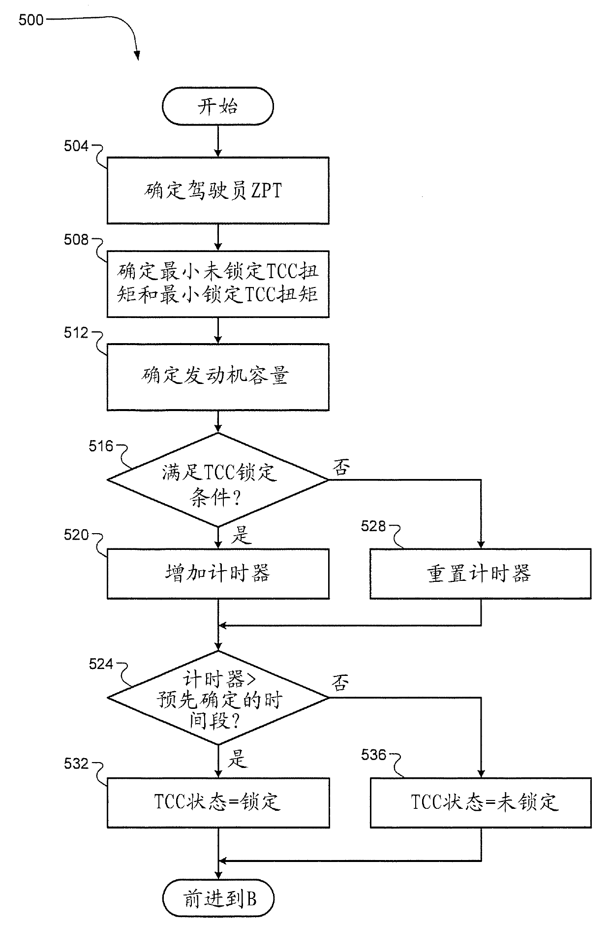
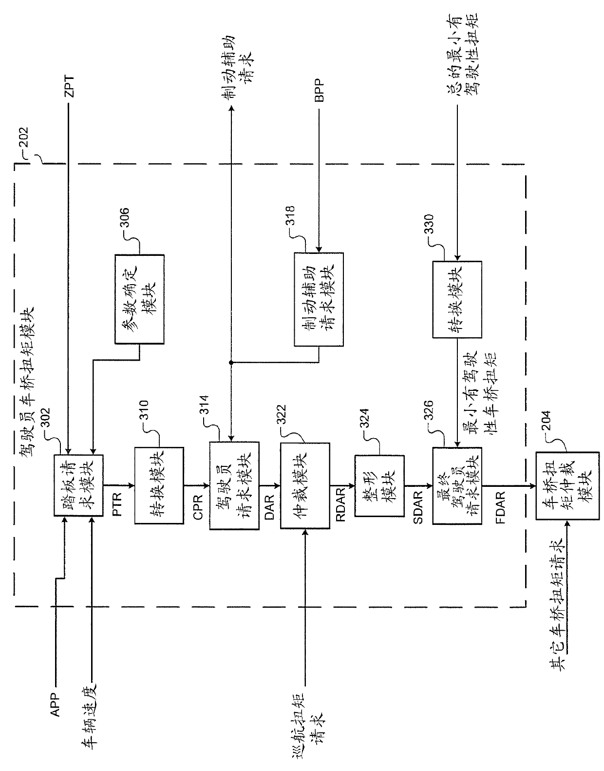
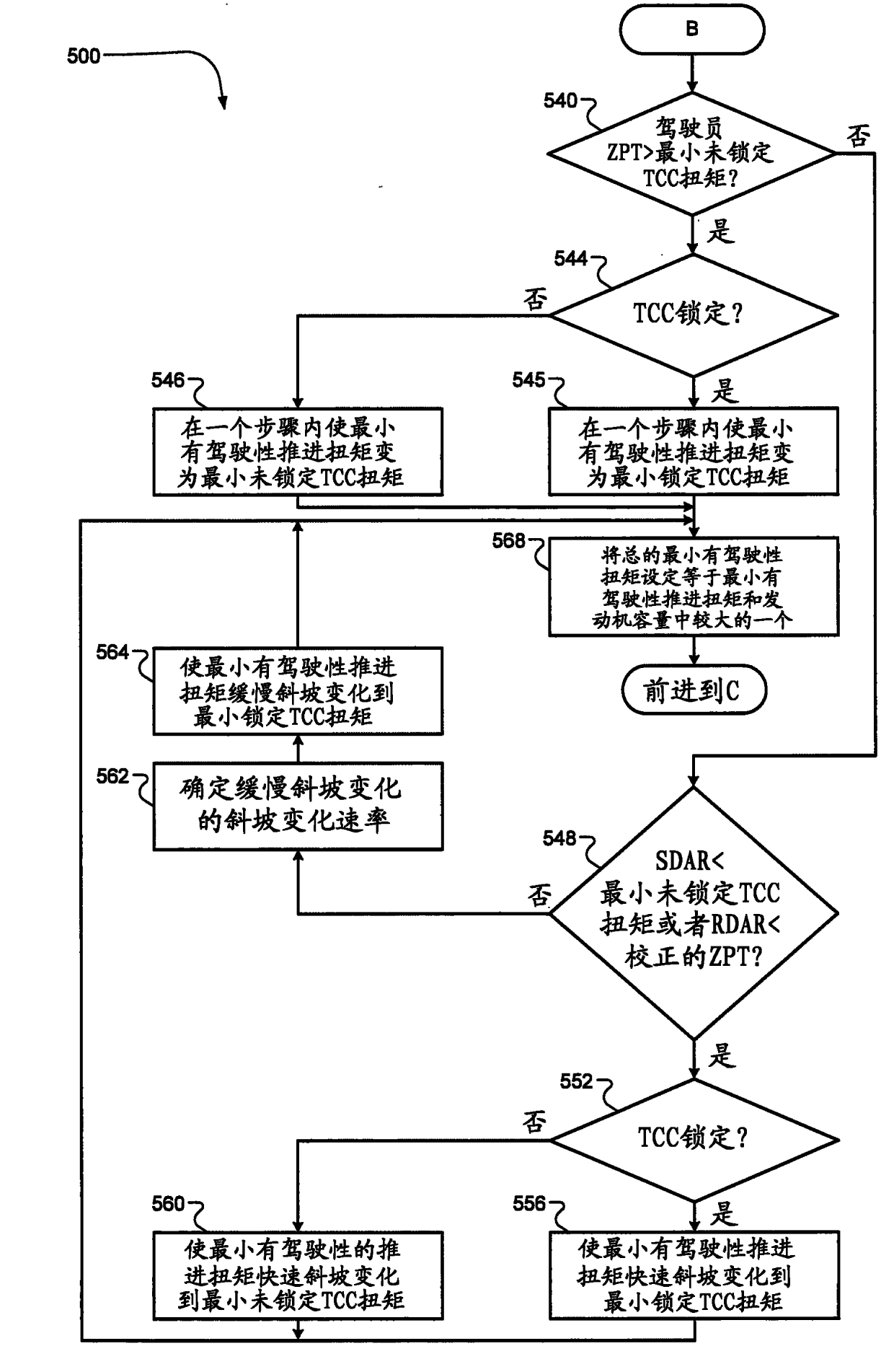
[0069] A control module of the vehicle may control the torque output of the engine based on the final driver axle torque request. The final driver axle torque reque...


PUM


Abstract

The invention relates to a driver torque request system, comprising a minimum torque module. The minimum torque module selectively determines a first minimum propulsion torque based on second and third minimum propulsion torques when a torque converter clutch is in unlocked and locked states, respectively. A zero pedal torque module selectively sets a zero pedal torque equal to the first minimum propulsion torque. A pedal request module determines a pedal torque request based on an accelerator pedal position, a vehicle speed, and the zero pedal torque. A driver request module determines a driver axle torque request based on the pedal torque request. A shaping module selectively shapes the driver axle torque request into a shaped driver axle torque request. A conversion module converts the first minimum propulsion torque into a minimum axle torque. A final driver request module sets a final driver axle torque request equal to a greater of the shaped driver axle torque request and the minimum axle torque.

Description

technical field [0001] The present disclosure relates to internal combustion engines, and more specifically, to driver torque requests. Background technique [0002] The background description provided herein is for the purpose of generally presenting the context of the disclosure. The work of the presently named inventors, to the extent described in this Background section, and aspects of the invention that may not have constituted prior art at the time of filing are not admitted, expressly or by implication, to be prior art to the present disclosure. [0003] Internal combustion engines combust an air and fuel mixture within cylinders to drive pistons and generate drive torque. Air flow into the engine is regulated by a throttle valve. More specifically, the throttle adjusts throttle area, which increases or decreases air flow into the engine. When the throttle area increases, the air flow into the engine increases. A fuel control system adjusts the rate of fuel inject...

Claims


Application Information

Patent Timeline
IPC IPC(8): F02D29/02
CPCB60W2510/0638B60W50/0097B60W2510/0233B60K6/48F02D41/1497B60W30/1884B60W2050/0091B60W50/087B60W2710/0622F02D29/02B60W2540/10Y02T10/62
Inventor C.E.惠特尼R.C.小西蒙W.L.阿尔德里奇三世J.卢B.P.巴塔赖A.J.海泽N.金
Owner GM GLOBAL TECH OPERATIONS LLC
Features
  • R&D
  • Intellectual Property
  • Life Sciences
  • Materials
  • Tech Scout
  • Unparalleled Data Quality
  • Higher Quality Content
  • 60% Fewer Hallucinations
Learn More