
Three-dimensional reconstruction method and device of moving target under variable illumination condition

A moving target, 3D reconstruction technology, applied in 3D modeling, image data processing, instruments, etc., can solve the problems of non-full viewing angle of the model, inability to directly collect, and difficulty in building a 3D model in textured areas, and achieve high-precision 3D reconstruction Effect

Inactive Publication Date: 2011-11-09
TSINGHUA UNIV
View PDF3 Cites 19 Cited by
  • Summary
  • Abstract
  • Description
  • Claims
  • Application Information

AI Technical Summary

Problems solved by technology

The traditional image-based multi-view stereo reconstruction method is difficult to establish an accurate 3D model in areas lacking texture, but it can establish a full-view 3D model
The traditional photometric stereo method is to use the multi-illumination image of a single viewing angle to establish a 3D model of a single viewing angle by estimating the normal information of the model surface and then estimating the depth map. Although the photometric stereo method can build a more detailed 3D model, the The model is a 3D model with a non-full perspective
As a result, it is impossible to directly collect multi-illumination images at the same time for moving targets

Method used


Image

  • Three-dimensional reconstruction method and device of moving target under variable illumination condition
  • Three-dimensional reconstruction method and device of moving target under variable illumination condition
  • Three-dimensional reconstruction method and device of moving target under variable illumination condition

Examples


Embodiment Construction

[0022] Embodiments of the present invention are described in detail below, examples of which are shown in the drawings, wherein the same or similar reference numerals designate the same or similar elements or elements having the same or similar functions throughout. The embodiments described below by referring to the figures are exemplary only for explaining the present invention and should not be construed as limiting the present invention.

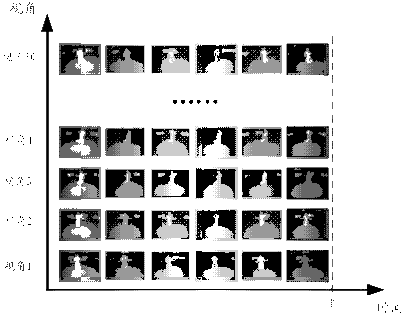
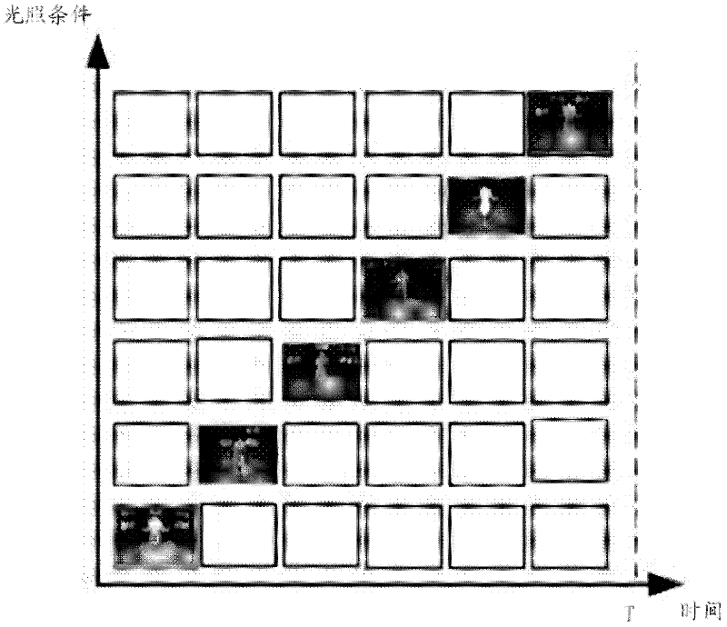
[0023] Refer below Figure 1 to Figure 4 A method for three-dimensional reconstruction of a moving object under variable light conditions according to an embodiment of the present invention is described.

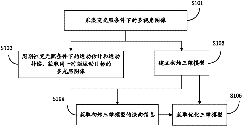
[0024] Such as figure 1 As shown, the three-dimensional reconstruction method of a moving target under variable light conditions provided by the embodiment of the present invention includes the following steps:

[0025] S101: Collect multi-view images of a moving target under variable light conditions.

[0026] Using multiple camera...


PUM


Abstract

The invention discloses a three-dimensional reconstruction method of a moving target under a variable illumination condition. The three-dimensional reconstruction method comprises the following steps of: collecting images of the moving target in multiple visual angles under the variable illumination condition provided by a light source; establishing an initial three-dimensional model of the moving target according to the images of the moving target in multiple visual angles, wherein the images are collected by multiple cameras at each moment; obtaining multiple illumination images of the moving target at each moment through utilizing movement estimation and movement compensation; recovering by uniting the initial three-dimensional model and multiple illumination images to obtain normal information of the initial three-dimensional model; and carrying out combined optimization on geometrical information of the initial three-dimensional model and the normal information of the initial three-dimensional model to obtain an optimized three-dimensional model of the moving target. The invention also discloses a three-dimensional reconstruction device of the moving target under the variable illumination condition. In the method and device provided by the invention, advantages of multiple-visual-angle three-dimensional and luminosity three-dimensional methods are combined and the movement estimation and the movement compensation under the periodical variable illumination condition are combined so that the reconstruction of a high-precision three-dimensional model of the moving target is realized.

Description

technical field [0001] The invention relates to the technical fields of computer graphics and computer vision, in particular to a three-dimensional reconstruction method and a three-dimensional reconstruction device of a moving target under variable light conditions. Background technique [0002] Obtaining accurate 3D models of dynamic scenes from multi-view video sequences is a hot research issue in computer vision, computer graphics and other disciplines. The traditional image-based multi-view stereo reconstruction method is difficult to establish an accurate 3D model in the area lacking texture, but it can build a full-view 3D model. The traditional photometric stereo method is to use the multi-illumination image of a single viewing angle to establish a 3D model of a single viewing angle by estimating the normal information of the model surface and then estimating the depth map. Although the photometric stereo method can build a more detailed 3D model, the The model is a...

Claims


Application Information

Patent Timeline
IPC IPC(8): G06T17/00
Inventor 刘烨斌付莹戴琼海
Owner TSINGHUA UNIV
Learn More