
Multi-function printer

a multi-functional printer and printer technology, applied in the direction of digital output to print units, instruments, computing, etc., can solve the problems of user problems, user takes a user needs a much longer time to obtain images, etc., to save the time for obtaining images and longer time

Inactive Publication Date: 2006-11-30
LITE ON SEMICON
View PDF10 Cites 1 Cited by
  • Summary
  • Abstract
  • Description
  • Claims
  • Application Information

AI Technical Summary

Benefits of technology

[0009] One particular aspect of the present invention is to provide a multi-function printer. The multi-function printer adopts a photo module to replace the scan module of the prior art to obtain the images. Therefore, regardless of the resolution of obtained image, the present invention can rapidly obtain the images to solve the drawback of needing a longer time to obtain the high-resolution images of the prior art. Moreover, the photo module of the present invention also can obtain the images by a three-dimensional method. For example, the photo module can be rotated vertically or horizontally to obtain a two-dimensional or three-dimensional image in different direction or angle. Alternatively, the photo module can be disassembled from the multi-function printer and operated alone as a general digital still camera. Therefore, the present invention has the merit of saving the time for obtaining the image, and the photo module used in the present invention has multi function.

Problems solved by technology

Moreover, because each of office machines occupies a corresponding space, it is a problem for the user when the office space is small.
Therefore, the user takes a longer time to obtain the image.
Especially, when a high-resolution image is obtained, the user needs much longer time to obtain the image.
Furthermore, due to the structure of the fastening mechanism of the scan module of the prior art, the scan module cannot be used for other functions.
It cannot obtain the image from the document by a three-dimensional method, or the scan module cannot be operated alone.

Method used


Image

  • Multi-function printer
  • Multi-function printer

Examples


Embodiment Construction

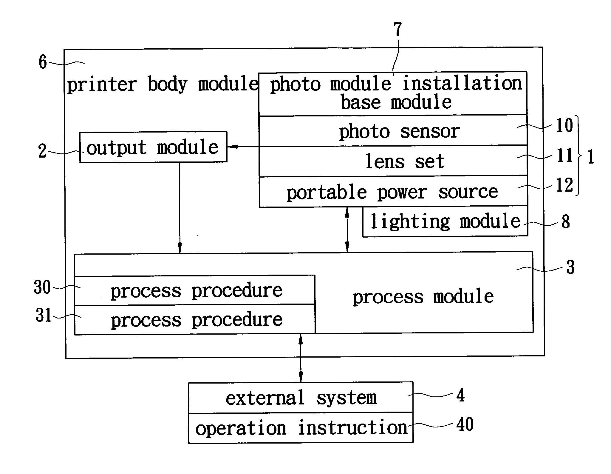
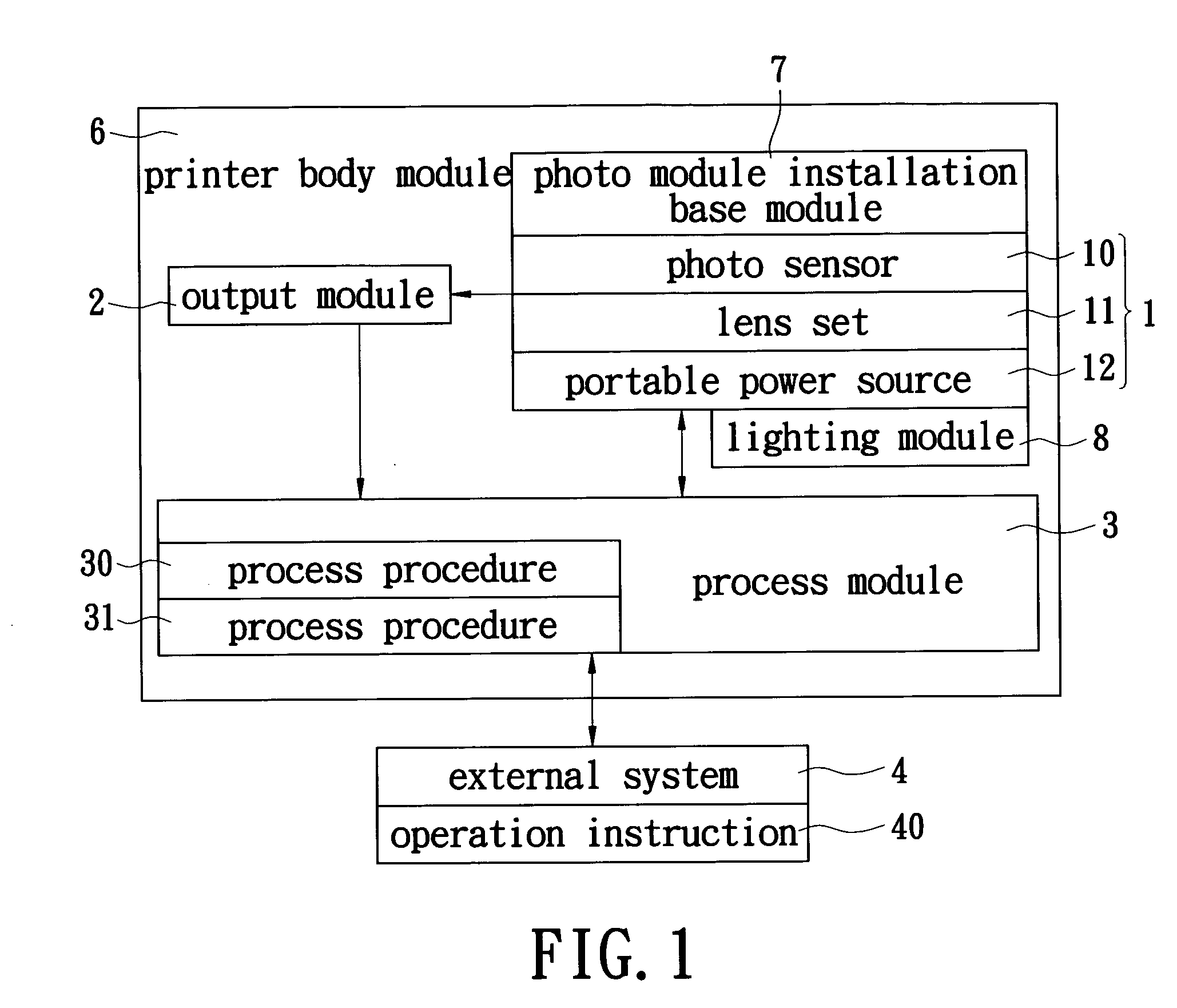
[0014] Please refer to FIG. 1, which shows a block diagram of the multi-function printer of the present invention. In the figure, the multi-function printer of the present invention includes a photo module 1, an output module 2 and a process module 3.

[0015] The photo module 1 is used for obtaining at least one image information and the at least one image information can be stored, transmitted or printed by the multi-function printer. The output module 2 is electrically connected with the photo module 1 for outputting the at least one image information obtained by the photo module 1. The photo module 1 is a printing device for printing the at least one image information obtained by the photo module 1. Furthermore, the printing device can print the information originally stored in the multi-function printer or the information transmitted from other devices to the multi-function printer.

[0016] The photo module 1 includes a photo sensor 10 and a lens set 11 linked with the photo senso...


PUM


Abstract

A multi-function printer includes a photo module, an output module and a process module. The photo module is used for obtaining at least one image information. The output module is electrically connected with the photo module for outputting the at least one image information obtained by the photo module. The process module is electrically connected with the photo module and the output module for controlling the information process and transition between the photo module, the output module and an external system. The multi-function printer adopts the photo module to replace the scan module of the prior art to obtain the images. Therefore, regardless of the resolution of obtained image, the present invention has a merit of rapidly obtaining the images. Moreover, the photo module also can obtain the images by a three-dimensional method and can be disassembled from the multi-function printer and operated alone as a general digital still camera.

Description

BACKGROUND OF THE INVENTION [0001] 1. Field of the Invention [0002] The present invention relates to a multi-function printer. In particular, a multi-function machine adopts a photo module to obtain images for saving the time of obtaining the images. [0003] 2. Description of the Related Art [0004] In the office, the office machines, such as copy machines, fax machines, printers or scanner, are the essential information apparatus. The office machines enhance the quality and the efficiency of the work and also make the storage and management of the files and the file-holder is more convenient and neater. However, the design and the operation method for each of office machines are different. Moreover, because each of office machines occupies a corresponding space, it is a problem for the user when the office space is small. [0005] Therefore, due to the development of the technology and the requirement of the user, the design of the information products has a tendency of multi-function....

Claims


Application Information

Patent Timeline
IPC IPC(8): G06F3/12
CPCH04N1/00278H04N2201/0084H04N1/00541H04N1/00538
Inventor CHENG, CHIA-CHUCHENG, SHIH-CHI
Owner LITE ON SEMICON
Learn More