
Spread spectrum circuit

A circuit and spread-spectrum technology, applied in the field of spread-spectrum circuits, can solve the problems of high transmission signal frequency, huge data transmission volume, etc.

Inactive Publication Date: 2011-11-09
NOVATEK MICROELECTRONICS CORP
View PDF4 Cites 3 Cited by
  • Summary
  • Abstract
  • Description
  • Claims
  • Application Information

AI Technical Summary

Problems solved by technology

However, with the improvement of resolution and picture update rate, the amount of data transmission has become quite large, and the frequency of transmission signals has also increased accordingly.

Method used


Image

  • Spread spectrum circuit
  • Spread spectrum circuit
  • Spread spectrum circuit

Examples


Embodiment Construction

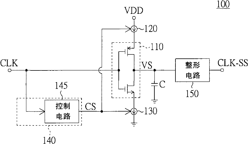
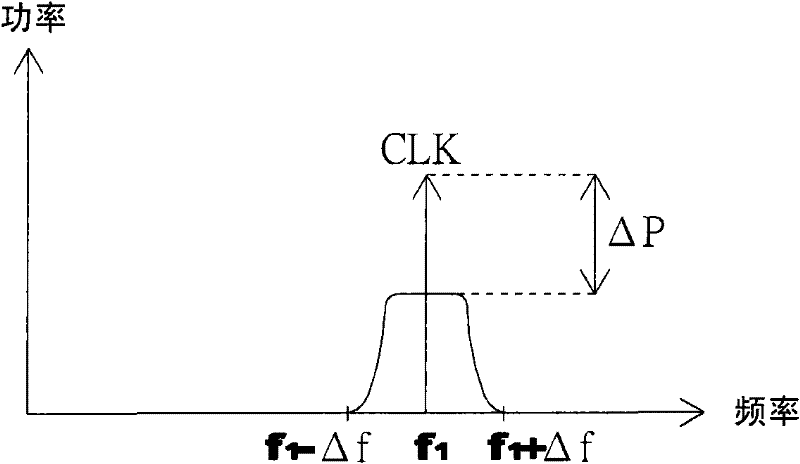
[0023] The present invention provides a spread spectrum circuit. Through a simple inverter, the input signal can be spread without additional control signals to reduce the electromagnetic radiation interference effect, and has the advantages of easy implementation and low complexity.

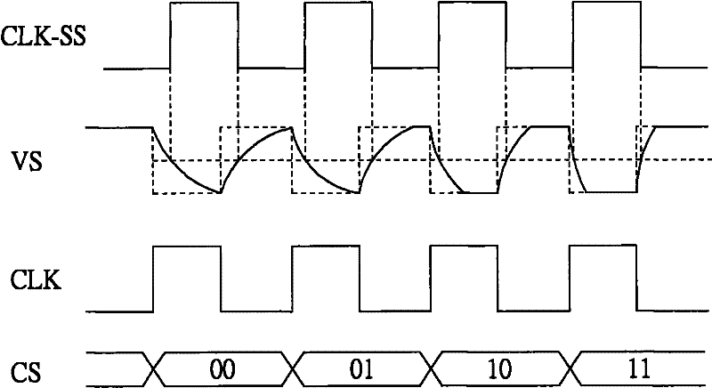
[0024] The present invention provides a spread spectrum circuit including an inverter, a current source, a control unit and a shaping circuit. The input terminal of the inverter receives an original clock signal. The current source is coupled to the current transmission end of the inverter. The control unit includes a control circuit that changes the current size of the current source according to the original clock signal to control the charging and discharging speed of the output terminal of the inverter, so that the output terminal outputs a voltage signal. The shaping circuit shapes the voltage signal to obtain a spread spectrum clock signal. Next, the inverter is a CMOS inverter as an exampl...


PUM


Abstract

The invention discloses a spread spectrum circuit, which comprises an inverter, a current supply, a control unit and a shaping circuit, wherein the input end of the inverter is used for receiving an original clock pulse signal; the current supply is coupled to the current transmission end of the inverter; the control unit comprises a control circuit which is used for controlling the charging / discharging speed of the output end of the inverter by changing the magnitude of the current of the current supply according to the original clock pulse signal to make the output end output a voltage signal; and the shaping circuit is used for shaping the voltage signal to obtain a spread spectrum clock pulse signal.

Description

【Technical Field】 [0001] The present invention relates to a spread spectrum circuit, and in particular to a low complexity spread spectrum circuit. 【Background technique】 [0002] With the evolution of technology, high-resolution (Full HD) pictures and high frame rate (framerate) are the inevitable trends of liquid crystal displays in the future. However, with the increase in resolution and picture update rate, the amount of data transmission has become quite large, and the frequency of the transmission signal has also become higher. When data is transmitted by high-frequency transmission, a very high electromagnetic radiation energy will be generated, which is the electromagnetic radiation interference (EMI) effect. How to reduce the electromagnetic radiation interference effect has become one of the main problems in the circuit design of liquid crystal displays. [Content of the invention] [0003] The present invention relates to a spread spectrum circuit. Through a simple inv...

Claims


Application Information

Patent Timeline
IPC IPC(8): H03K5/1252G09G3/36
Inventor 洪敬和林永正曾柏瑜
Owner NOVATEK MICROELECTRONICS CORP
Learn More