
Liquid crystal panel, manufacturing method thereof and liquid crystal displayer

A liquid crystal display and liquid crystal panel technology, applied in the direction of instruments, nonlinear optics, optics, etc., can solve the problems of lowering the contrast ratio and affecting the display quality of the liquid crystal display, and achieve the effect of improving the contrast ratio and improving the display quality.

Active Publication Date: 2011-11-16
BOE TECH GRP CO LTD +1
View PDF4 Cites 2 Cited by
  • Summary
  • Abstract
  • Description
  • Claims
  • Application Information

AI Technical Summary

Problems solved by technology

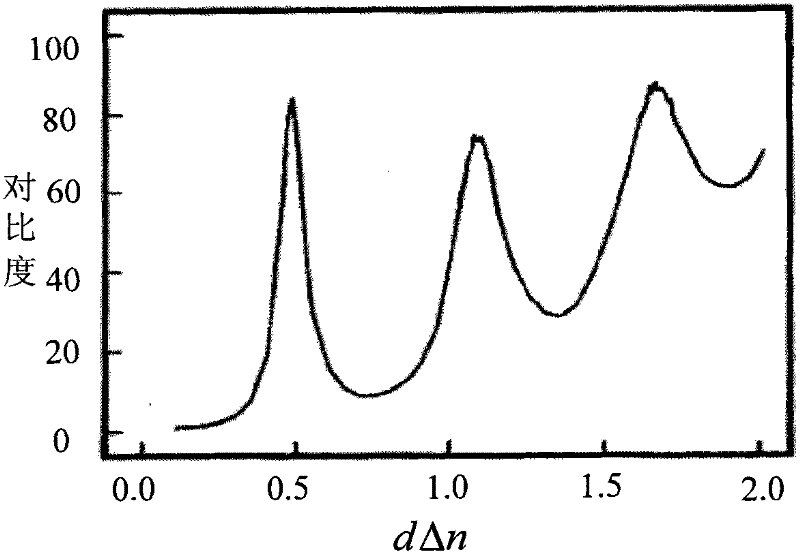
[0004] In the prior art, the entire liquid crystal panel adopts the same cell thickness design, and the value of Δn corresponding to the high-temperature area in the panel is lower than the normal area, so that the Δn×d of the high-temperature area is lower than the normal area, which leads to a significant contrast in this area. The decline will affect the display quality of the entire LCD display

Method used


Image

  • Liquid crystal panel, manufacturing method thereof and liquid crystal displayer
  • Liquid crystal panel, manufacturing method thereof and liquid crystal displayer
  • Liquid crystal panel, manufacturing method thereof and liquid crystal displayer

Examples


Embodiment Construction

[0032] In order to make the purpose, technical solutions and advantages of the embodiments of the present invention clearer, the technical solutions in the embodiments of the present invention will be clearly and completely described below in conjunction with the drawings in the embodiments of the present invention. Obviously, the described embodiments It is a part of embodiments of the present invention, but not all embodiments. Based on the embodiments of the present invention, all other embodiments obtained by persons of ordinary skill in the art without creative efforts fall within the protection scope of the present invention.

[0033] This embodiment provides a liquid crystal panel, which includes a first liquid crystal display substrate, a second liquid crystal display substrate, and liquid crystal filled between the first liquid crystal display substrate and the second liquid crystal display substrate, wherein the A protective layer is provided on the first liquid crys...


PUM


Abstract

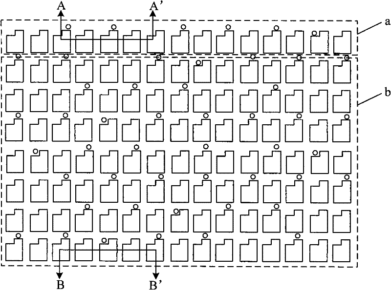
The invention discloses a liquid crystal panel, a manufacturing method thereof and a liquid crystal displayer. The liquid crystal panel comprises a first liquid crystal display substrate, a second liquid crystal display substrate and a liquid crystal filled between the first liquid crystal display substrate and the second liquid crystal display substrate, wherein a protecting layer is disposed onthe first liquid crystal display substrate or the second liquid crystal display substrate corresponding to the non-high-temperature area of the liquid crystal panel; a spacing article is disposed in the first liquid crystal display substrate or the second liquid crystal display substrate so that the product of the optical anisotropy constant of the liquid crystal corresponding to the non-high-temperature area of the liquid crystal panel and a box thickness keeps identical with the product of the optical anisotropy constant of the liquid crystal corresponding to the high-temperature area thereof and the box thickness. In the invention, the protecting layer and the spacing article are disposed on the substrate corresponding to the non-high-temperature area of the liquid crystal panel so that the products of the optical anisotropy constants of the liquid crystals corresponding to the non-high-temperature area and the high-temperature area of the liquid crystal panel and the box thicknesskeep identical, which realizes to design different box thicknesses according to the temperatures of the different areas of the liquid crystal panel.

Description

technical field [0001] The invention relates to liquid crystal display technology, in particular to a liquid crystal panel, a manufacturing method thereof and a liquid crystal display. Background technique [0002] A liquid crystal display is a commonly used flat panel display at present, and a Thin Film Transistor Liquid Crystal Display (TFT-LCD for short) is a mainstream product in the liquid crystal display. A liquid crystal panel is usually formed by combining an array substrate and a color filter substrate, and injecting liquid crystal between the two substrates. In the manufacturing process of the liquid crystal panel, the thickness of the cell (Cell Gap) is an important control factor, and the change of the thickness will cause the transmittance and contrast of the liquid crystal panel to change, and then affect the quality of the liquid crystal display. In order to keep the cell thickness consistent between the array substrate and the color filter substrate in the l...

Claims


Application Information

Patent Timeline
Patent Type & Authority Applications(China)
IPC IPC(8): G02F1/1339G02F1/1333
Inventor 赵海玉梁晶晶肖光辉
Owner BOE TECH GRP CO LTD
Learn More