
Lighting system with fiber diffusing element

A fibrous, transparent technology used in the field of light-emitting devices to solve problems such as interfering with the viewing of pictures, text or graphics

Inactive Publication Date: 2011-11-16
SIGNIFY HLDG BV
View PDF6 Cites 2 Cited by
  • Summary
  • Abstract
  • Description
  • Claims
  • Application Information

AI Technical Summary

Problems solved by technology

However, the fact that individual LEDs are visible can interfere with viewing pictures, text or graphics

Method used


Image

  • Lighting system with fiber diffusing element
  • Lighting system with fiber diffusing element
  • Lighting system with fiber diffusing element

Examples


Embodiment Construction

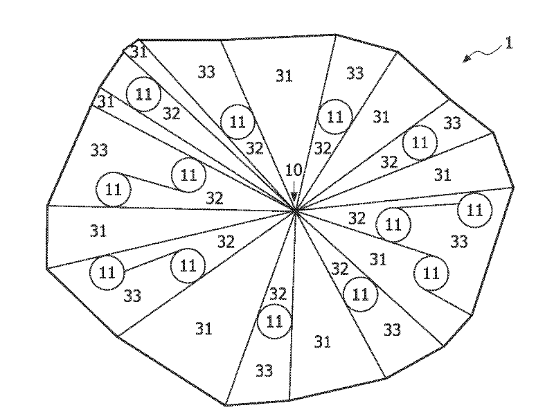
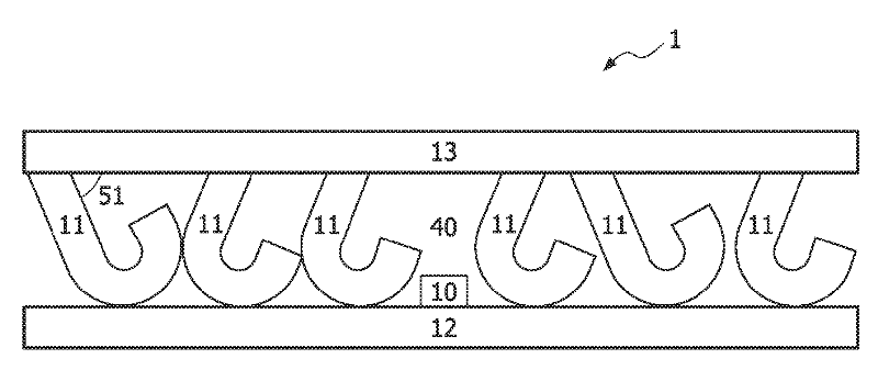
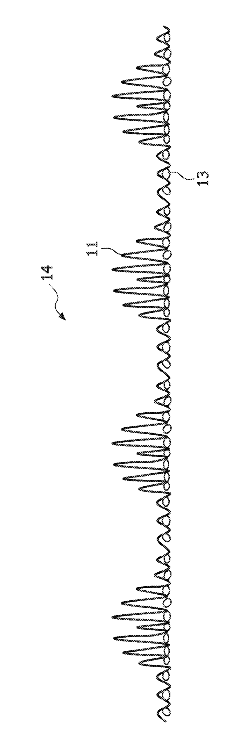
[0033] figure 1 A schematic three-dimensional view of an exemplary embodiment of a lighting device 1 is shown. An illumination source or light emitter 10 is mounted to a substrate 12 and surrounded by a plurality of fibers 11 . Finally, a support 13 is placed on top of the fibers 11 . The fibers may be pre-attached to the support 13, which may also function as a diffusing layer. In this figure, the fibers 11 are shown in a periodic distribution relative to each other, however they could also be distributed in a random pattern relative to each other, as can be seen in figure 2seen in . The substrate 12 should preferably be made of a material that is as reflective as possible in order to prevent backscattered light from being lost through absorption by the material. It should be noted that although the substrate 12 and the support 13 are placed at the bottom and top respectively, it is also possible that the fibers are attached to the substrate and thus the substrate also ...


PUM


Abstract

The present invention relates to a light emitting device (1) comprising a light emitter (10) and a support (13) to which a plurality of protruding fibers (11) are attached. The light emitter (10) and the protruding fibers (11) are arranged to interact with light emitted from the light emitter (10) so that the light may be diffused. The plurality of protruding fibers comprises fibers (11) which are inclined or perpendicular in relation to the support (13).

Description

technical field [0001] The present invention relates to the field of light emitting devices, and more particularly to the improvement of the material properties of one or more diffusing elements. Background technique [0002] LED lighting with low resolution (i.e. the light emitting diodes (LEDs) are spaced so that individual LED dots can be easily distinguished) can be used in many different applications such as pictures related to e.g. textiles such as clothing , text and graphics. However, the fact that individual LEDs are visible may interfere with viewing pictures, text or graphics. The solution to this problem is to add a diffusing layer on top of the LEDs to spread the light over a larger area. This diffusing layer can be made of different materials, such as woven or non-woven materials, flexible foam, or some combination thereof. [0003] An example of this solution can be found in US2008 / 0205035A1. Here the LEDs are placed under a diffuser layer comprising a non...

Claims


Application Information

Patent Timeline
Patent Type & Authority Applications(China)
IPC IPC(8): G09F9/33G09F13/22
CPCG09F9/33G09F13/22G09F13/0409G02B5/0205G09F13/14G09F13/16
Inventor R.巴塔查亚K.范奥斯H.J.科内利森
Owner SIGNIFY HLDG BV
Features
  • Generate Ideas
  • Intellectual Property
  • Life Sciences
  • Materials
  • Tech Scout
  • Unparalleled Data Quality
  • Higher Quality Content
  • 60% Fewer Hallucinations
Learn More