Controllable powder-feeding mechanism of power forming machine

A controllable and forming machine technology, applied in the direction of presses, manufacturing tools, etc., can solve the problems of collision between the punch and the powder feeding hopper, affecting the powder forming machine, increasing the height of the whole machine, etc., to achieve fast powder feeding, The powder feeding speed can be controlled to reduce the effect of conveying energy

Active Publication Date: 2011-11-23
宁波汇众粉末机械制造有限公司
View PDF5 Cites 15 Cited by
  • Summary
  • Abstract
  • Description
  • Claims
  • Application Information

AI Technical Summary

Problems solved by technology

[0002] The powder feeding hopper used in the existing powder molding machine is an integral structure. In order to meet the requirements of powder metallurgy parts that need to be filled with more powder, the volume and height of the powder feeding hopper are relatively large. If the vertical height of the powder feeding hopper is too high, it will not only Increasing the height of the whole machine will also cause the punch and the powder feeding hopper to collide or interfere with each other when the powder forming machine is pressed down due to the downward pressure of the punch, which will affect the normal operation of the powder forming machine. The height of the powder feeding hopper should not be too high, but the powder should be filled more, so as to meet the requirements of parts production materials

Method used


Image

  • Controllable powder-feeding mechanism of power forming machine
  • Controllable powder-feeding mechanism of power forming machine
  • Controllable powder-feeding mechanism of power forming machine

Examples


Embodiment Construction

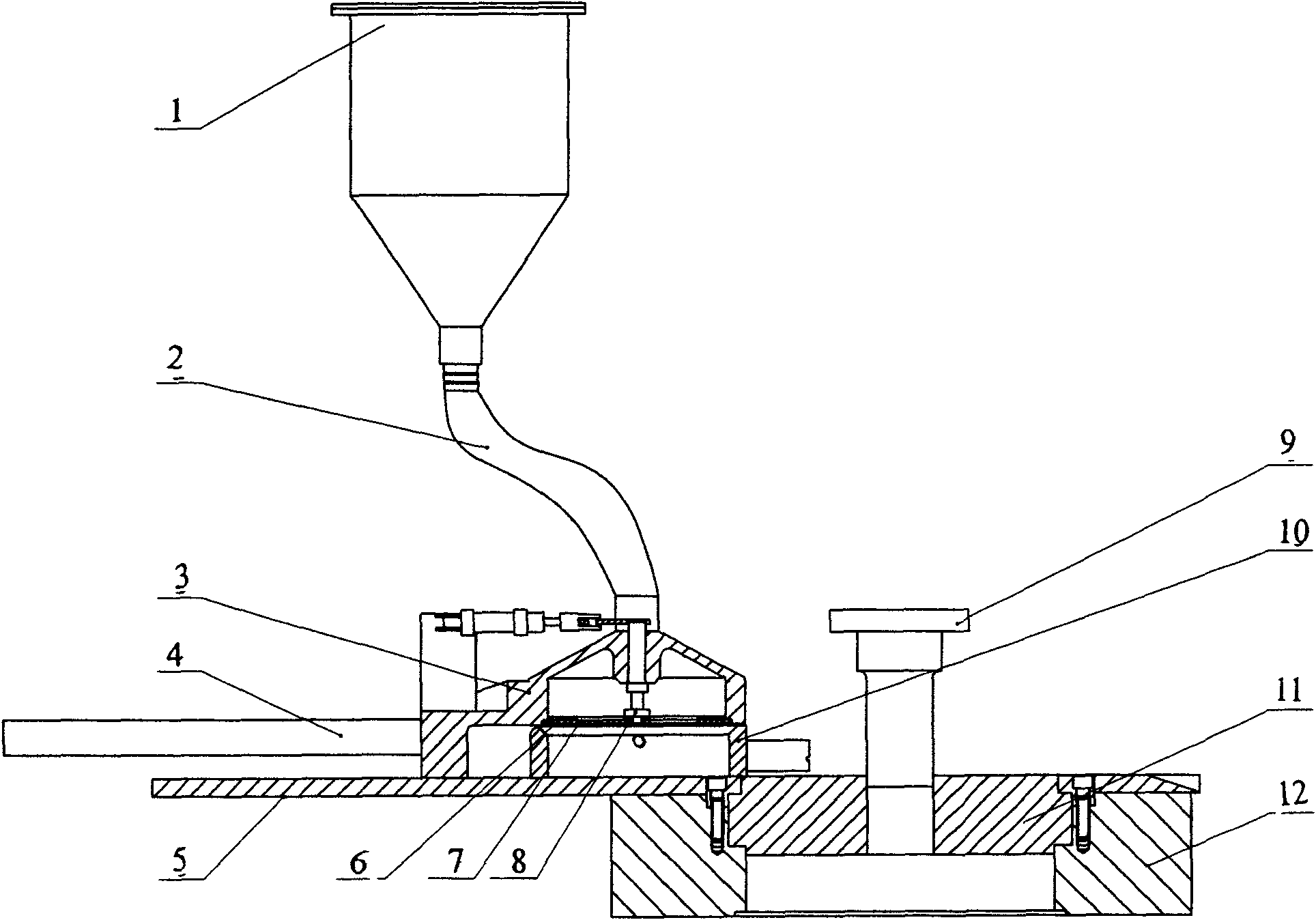
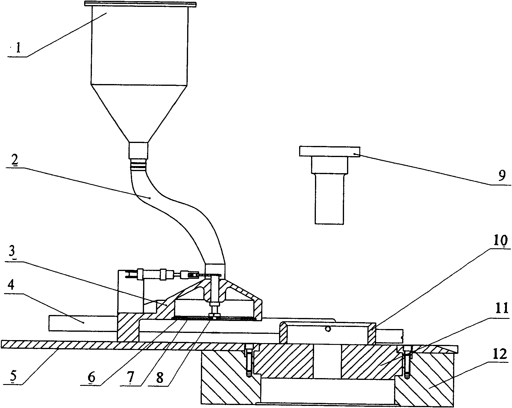
[0016] Embodiments of the present invention will be further described below in conjunction with the accompanying drawings.

[0017] The powder feeding plate 5 is fixed on the female template 12 with screws, and the upper punch 9 on the powder molding machine cooperates with the female mold 11, which are all prior art parts.

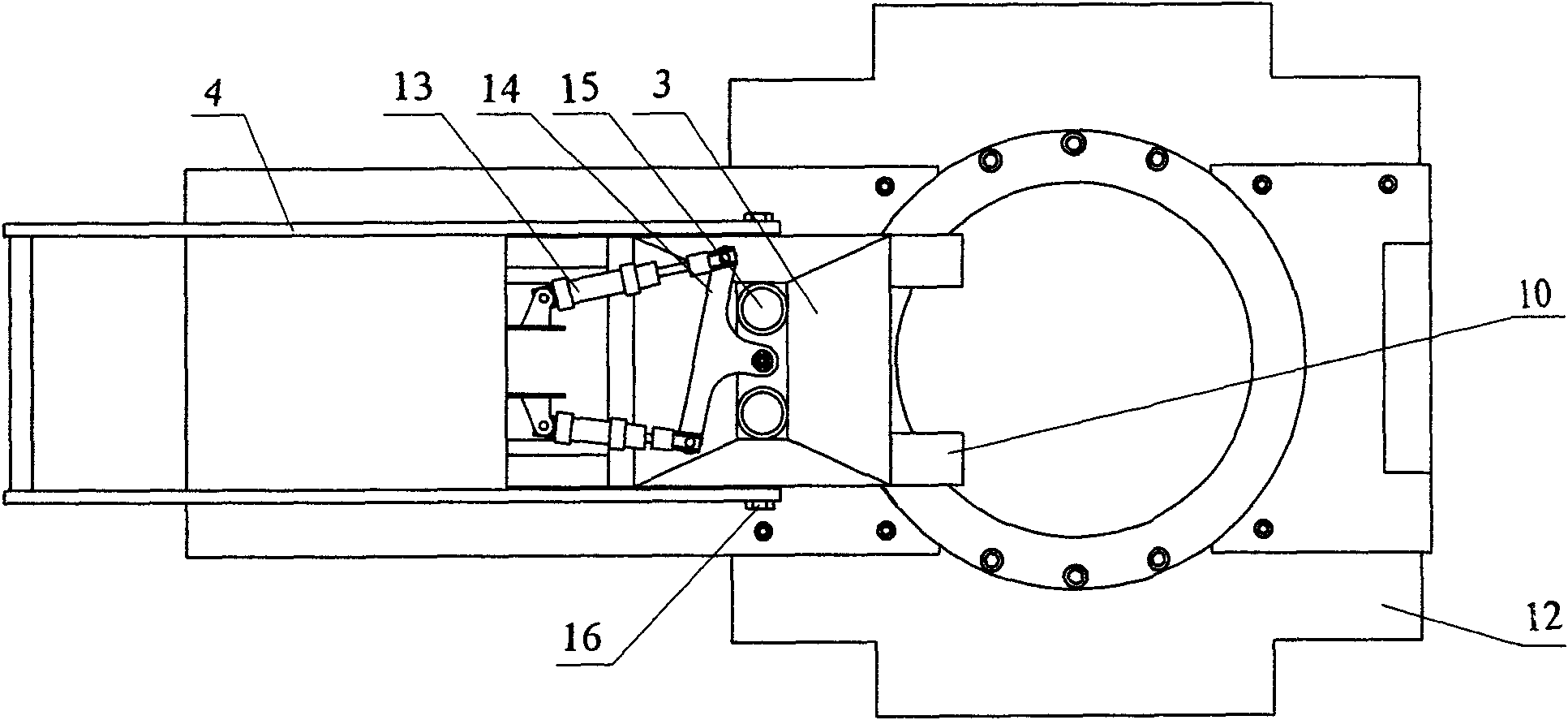
[0018] The upper hopper 3 is an integral part, one side is stepped, the other side is a cantilever chamber, and there is more than one feeding port in the middle of the upper surface. There are two symmetrical feeding ports 15 on the upper hopper, and the inner wall of the cantilever chamber has two inlets. There is a boss with a through hole between the feed openings, and the rotating shaft 8 passes through the through hole on the boss in the middle of the upper hopper and is installed on the upper hopper 3 .

[0019] The driving mechanism can be different power sources such as cylinder promotion or mechanical transmission, and the existing driving mecha...


PUM


Abstract

The invention relates to a controllable powder-feeding mechanism of a power forming machine, comprising a whole body formed by connecting a powder-feeding bracket and a feeding hopper with a feeding inlet and a discharging valve, wherein the feeding hopper is formed by matching a charging hopper with a discharging hopper; the powder-feeding bracket and the discharging hopper are connected into a whole, a rotating shaft is installed on the discharging valve from the charging hopper, connected with a driving mechanism fixed on the charging hopper, driven by the driving mechanism to rotate and connected with a movable blade and matched with a stator blade fixed on the charging hopper. An integrated powder-feeding hopper is improved into a split type powder-feeding hopper consisting of the charging hopper and the discharging hopper, the integrated movement is changed into the movement that the discharging hopper is only pulled by the powder-feeding bracket, a stationary movement structureof the charging hopper ensures that a vertical height of the movement part of the powder-feeding mechanism is much lower than the integrated structure, therefore, the condition of collision or interference of the feeding hopper and a punch is thoroughly eradicated, the conveying energy of the powder-feeding bracket is greatly reduced, the operation is convenient, the powder-feeding speed is high and can be controlled, and the controllable powder-feeding mechanism has strong practicability.

Description

technical field [0001] The invention relates to a mechanical powder feeding device, in particular to a powder forming machine controllable powder feeding mechanism installed on a powder forming machine for feeding powder materials. Background technique [0002] The powder feeding hopper used in the existing powder molding machine is an integral structure. In order to meet the requirements of powder metallurgy parts that need to be filled with more powder, the volume and height of the powder feeding hopper are relatively large. If the vertical height of the powder feeding hopper is too high, it will not only Increasing the height of the whole machine will also cause the punch and the powder feeding hopper to collide or interfere with each other when the powder forming machine is pressed down due to the downward pressure of the punch, which will affect the normal operation of the powder forming machine. The height of the powder feeding hopper should not be too high, but the po...

Claims


Application Information

Patent Timeline
Patent Type & Authority Applications(China)
IPC IPC(8): B22F3/03B30B15/30
Inventor 严培义
Owner 宁波汇众粉末机械制造有限公司
Why Eureka
Try Eureka