Elevating roller machine

A technology of rolling bed and lifting bracket, applied in the field of lifting rolling bed, can solve problems such as impact of the lifting rolling bed, and achieve the effects of light driving, reduced friction and simple structure

Inactive Publication Date: 2011-11-23
ZHONGQI CHANGXING LUOYANG ELECTROMECHANICAL EQUIP ENG
View PDF10 Cites 11 Cited by
  • Summary
  • Abstract
  • Description
  • Claims
  • Application Information

AI Technical Summary

Problems solved by technology

[0004] The purpose of the present invention is to provide a lifting roller bed with simple structure

Method used


Image

  • Elevating roller machine
  • Elevating roller machine
  • Elevating roller machine

Examples


Embodiment Construction

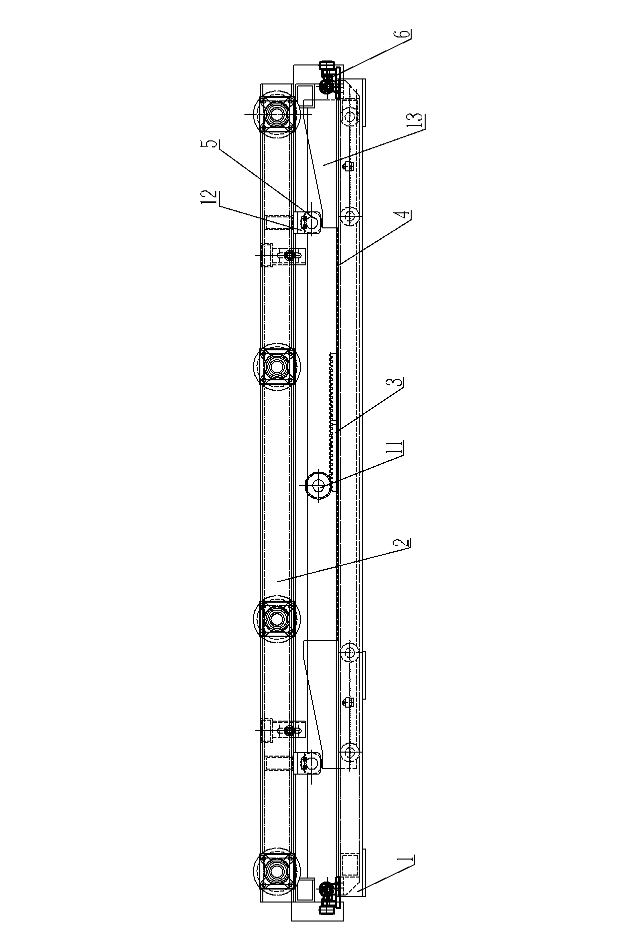
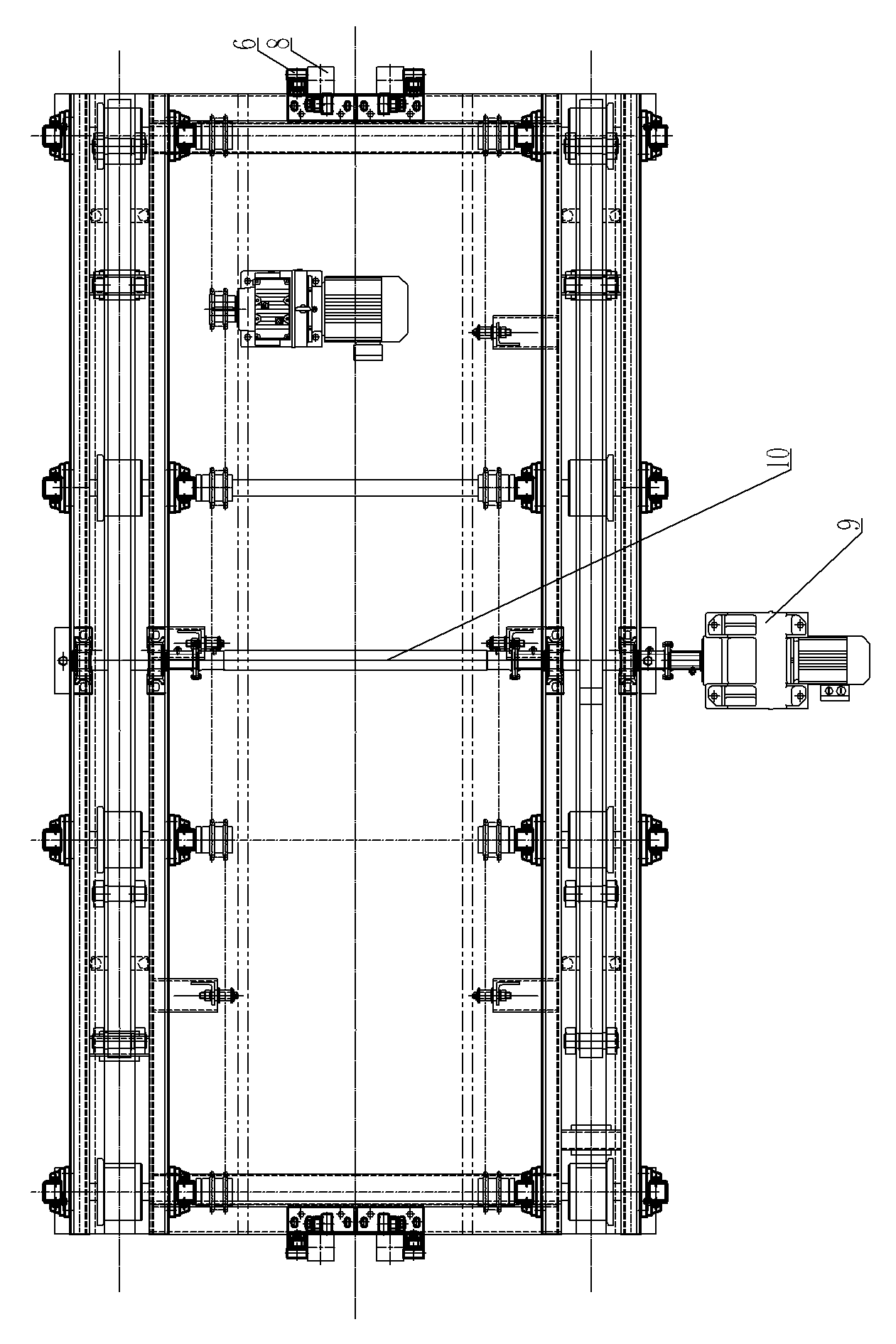
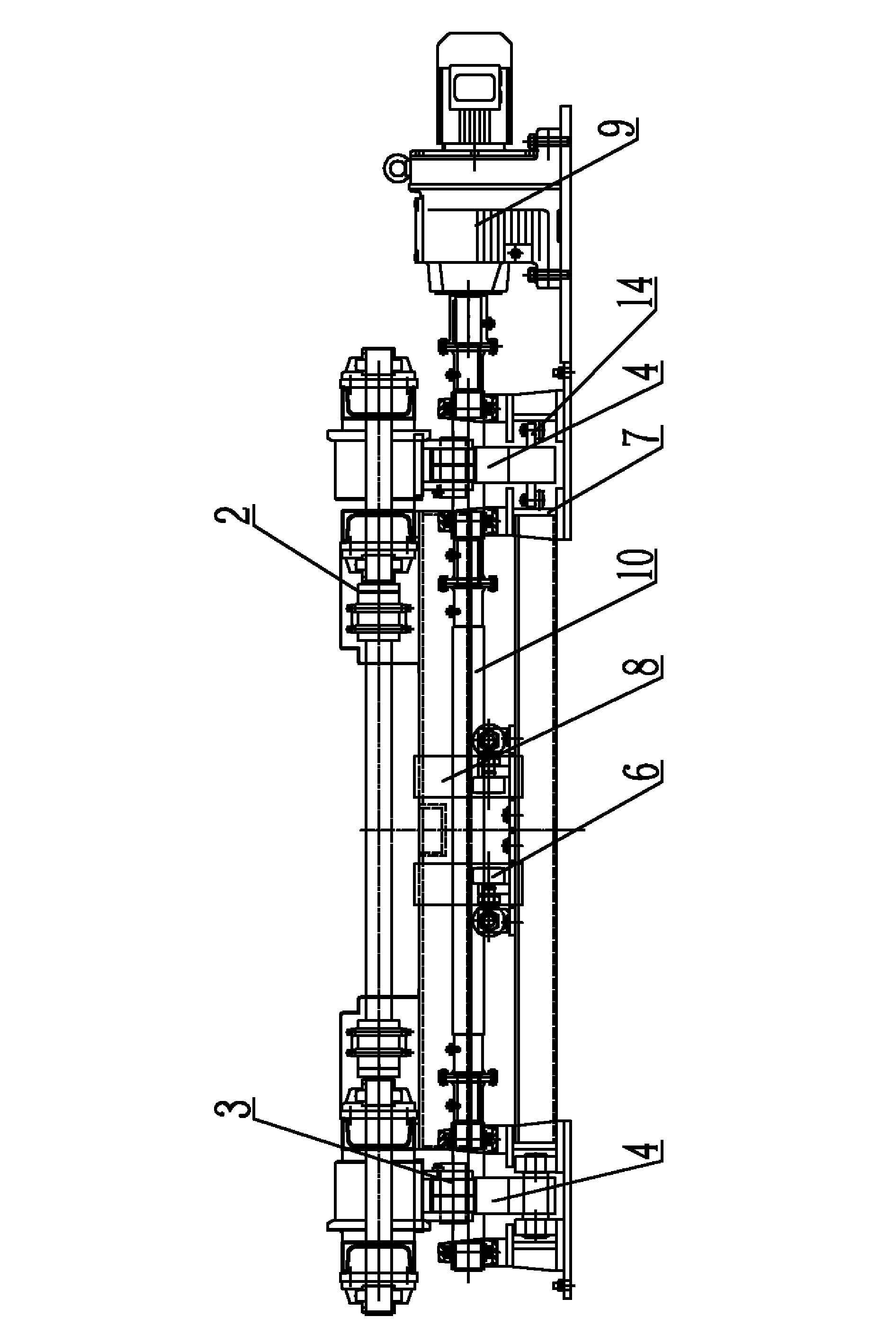
[0019] An embodiment of a lifting roller bed, in figure 1 , 2 , 3, including the rolling bed body 2, the lower part of the rolling bed body 2 is provided with a lifting bracket device 1, the lower part of the lifting bracket device 1 is fixedly arranged on the foundation, and the lifting bracket device 1 is used to drive the rolling bed body 2 relative to the lifting bracket Device 1 moves up and down. As in the prior art, a guide device for the up and down movement of the roller bed body 2 is provided between the lifting support device 1 and the roller bed body 2. The guide device is the same as the guide device in the prior art, including a The square guide column 8 on the bed body 2, the square guide column 8 is arranged on the bottom of the rolling bed body 2 and stretches to the lifting bracket device 1, and the lifting bracket device is rotated with a guide wheel 6, and the guide wheel 6 and the square guide column 8 are connected to each other. Side scrolling fit. Th...


PUM


Abstract

The invention relates to an elevating roller machine, which comprises a roller machine body and an elevating bracket device, wherein the elevating bracket device is arranged below the roller machine body and is used for driving the roller machine body to move upwards and downwards; the elevating bracket device is used for driving the roller machine body to move upwards and downwards through linearly sliding a movable trolley structure which is arranged on the elevating bracket device; the elevating bracket device is provided with a driving device used for driving the movable trolley structure to move in a reciprocating manner; a transmission post which moves upwards and downwards synchronously with the roller machine body is arranged on the roller machine body in a downwards-projecting manner; and the movable trolley structure is provided with a bump which can be matched with the transmission post in a moving and pushing manner and is used for jacking the transmission post when the movable trolley structure moves relative to the elevating bracket device. When the movable trolley moves, the bump is used for pushing the roller machine body to move upwards; and when the movable trolley structure moves reversely, the roller machine body moves downwards under the action of gravity. A novel roller machine body driving way is provided. Moreover, moving and pushing matching between the bump and the transmission post can be realized, so that the bump and the transmission post are matched smoothly without impacting.

Description

technical field [0001] The invention relates to a chain (belt) traveling machine used to transport the sled with workpieces from other equipment to the chain (belt) traveling machine, or transport the sled with workpieces from the chain (belt) traveling machine The lifting roller bed to other equipment belongs to the material transportation industry. Background technique [0002] The lifting roller bed is generally used with the chain (belt) type transfer machine to transfer the sled with the workpiece from other equipment to the chain (belt) type transfer machine, or to transfer the sled with the workpiece from the chain (belt) type transfer machine. On-board transport to other equipment. The current lifting roller bed generally includes an upper rolling bed body and a lower lifting device that drives the rolling bed body to move up and down. The existing lifting device is a pneumatic jacking lifting device. Shock, movement smoothness is not good. In order to solve the i...

Claims


Application Information

Patent Timeline
IPC IPC(8): B65G47/52B65G13/12
Inventor 高春生陈显袁喜报朱军涛
Owner ZHONGQI CHANGXING LUOYANG ELECTROMECHANICAL EQUIP ENG
Why Eureka
Try Eureka