Heat exchanger

A heat exchanger and fin technology, which is applied in the field of heat exchangers, can solve the problems of accumulation of frost layer and reduce the heat exchange capacity of heat exchangers, and achieve the effect of delaying frost formation and ensuring performance.

Inactive Publication Date: 2011-11-23
SANHUA HLDG GRP +1
View PDF6 Cites 9 Cited by
  • Summary
  • Abstract
  • Description
  • Claims
  • Application Information

AI Technical Summary

Problems solved by technology

If the fin density is too high, the frost layer will accumulate quickly, and if the fin density is too small, the heat transfer capacity of the heat exchanger will be reduced

Method used


Image

  • Heat exchanger
  • Heat exchanger
  • Heat exchanger

Examples


Embodiment 1

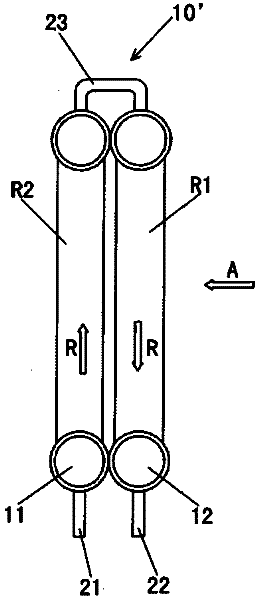
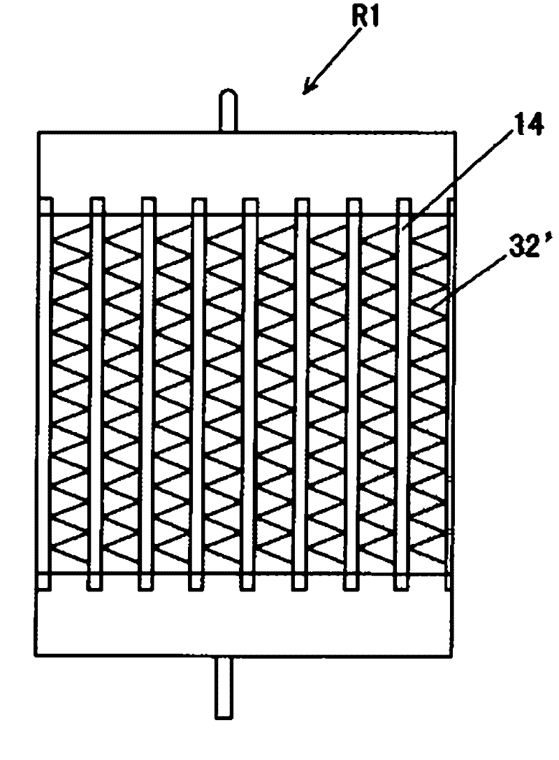
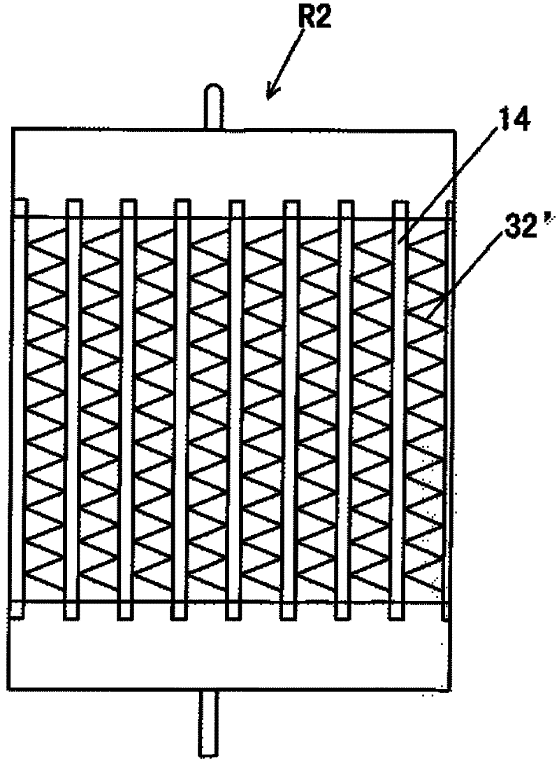
[0028] Figure 2A , 2B , 2C, 3A, 3B, 3C show a heat exchanger according to a first embodiment of the present invention. refer to Figure 2A , 2B , 2C, 3A, 3B, 3C, the heat exchanger 10 according to an embodiment of the present invention may be a microchannel heat exchanger, and includes: a first row of heat exchangers R1 and a second row of heat exchangers R2 arranged side by side, The first row of heat exchangers R1 includes fins 32 and the second row of heat exchangers R2 includes fins 34, the fin density of the fins 32 of the first row of heat exchangers R1 is the same as that of the fins of the second row of heat exchangers R1. different fin densities. Fin density is the number of half crests of corrugated fins per inch of length, and the definition of this term is common knowledge in the art.

[0029] The heat exchanger 10 also includes: a header 11 at the inlet end of the heat exchanger and a header 12 at the outlet end of the heat exchanger, which are respectively ...

Embodiment 2

[0034] Figure 4A , 4B , 4C, 4D, 5A, 5B, 5C, 5D, 6A, 6B, 6C, 6D show a heat exchanger according to a second embodiment of the present invention. refer to Figure 4A , 4B , 4C, 4D, 5A, 5B, 5C, 5D, 6A, 6B, 6C, 6D, the heat exchanger 10 according to an embodiment of the present invention may be a microchannel heat exchanger, and includes: a first row arranged side by side Heater R1, the second row of heat exchangers R2 and the third row of heat exchangers R3, the first row of heat exchangers R1 includes fins 32, the second row of heat exchangers R2 includes fins 34, the third row of heat exchangers R1 includes fins 36, the fin density of the fins 32 of the first row of heat exchangers R1, the fin density of the fins 34 of the second row of heat exchangers R2, and the fins of the third row of heat exchangers R3 At least two of the 36 fin densities are different. The second row of heat exchangers R2 is disposed between the first row of heat exchangers R1 and the third row of h...


PUM


Abstract

The invention provides a heat exchanger. The heat exchanger comprises a first row of heat exchanger and a second row of heat exchanger which are arranged side by side; and the first row of the heat exchanger comprises fins and the second row of the heat exchanger comprises fins. The density of the fins of the first row of the heat exchanger is different from that of the fins of the second row of the heat exchanger. The different densities of the fins are set according to different layer numbers, so that the frost formation of a micro channel heat exchanger can be reduced, and the capacity of the running of a system and the efficiency are improved.

Description

technical field [0001] The invention relates to a heat exchanger. Background technique [0002] refer to Figure 1A , 1B , 1C, the heat exchanger 10' such as a microchannel heat exchanger includes: a first row of heat exchangers R1 and a second row of heat exchangers R2. The heat exchanger 10' also includes: a header 11 at the inlet end of the heat exchanger and a header 12 at the outlet end of the heat exchanger, which are respectively connected to the header 11 at the inlet end of the heat exchanger and the header 12 at the outlet end of the heat exchanger The heat exchanger inlet pipe 21 and the heat exchanger outlet pipe 22, as well as the intermediate connection pipe 23 of the heat exchanger. [0003] Such as Figure 1A As shown, the refrigerant flows in the direction R, and the wind blows in the direction A to the heat exchanger 10'. Both the first row of heat exchangers R1 and the second row of heat exchangers R2 include heat exchange tubes 14 such as flat tubes an...

Claims


Application Information

Patent Timeline
Patent Type & Authority Applications(China)
IPC IPC(8): F25B39/00F25B47/00F28F1/12
Inventor 高强黄宁杰
Owner SANHUA HLDG GRP
Why Eureka
Try Eureka