Testing method and apparatus for supporting state, dynamic balancing state and non-centering state of rotating machine

A technology of rotating machines and testing methods, applied in the field of reliability and safety of mechanical equipment, can solve the problems of inability to identify the blind area of ​​machine support stiffness state and alignment state, and inability to comprehensively and correctly guide debugging, etc.

Active Publication Date: 2013-05-22
北京唐智科技发展有限公司
View PDF5 Cites 2 Cited by
  • Summary
  • Abstract
  • Description
  • Claims
  • Application Information

AI Technical Summary

Problems solved by technology

[0011] The technical problem to be solved by the present invention is to detect the equivalent support state of the machine, the dynamic balance and the misalignment information between each machine during the operation of the rotating machine, so as to overcome the inability of the traditional static detection method to identify the support under the dynamic condition of the machine. Blind spots of stiffness state and alignment state and thus the dilemma of not being able to fully and correctly guide commissioning

Method used


Image

  • Testing method and apparatus for supporting state, dynamic balancing state and non-centering state of rotating machine
  • Testing method and apparatus for supporting state, dynamic balancing state and non-centering state of rotating machine
  • Testing method and apparatus for supporting state, dynamic balancing state and non-centering state of rotating machine

Examples


Embodiment 1

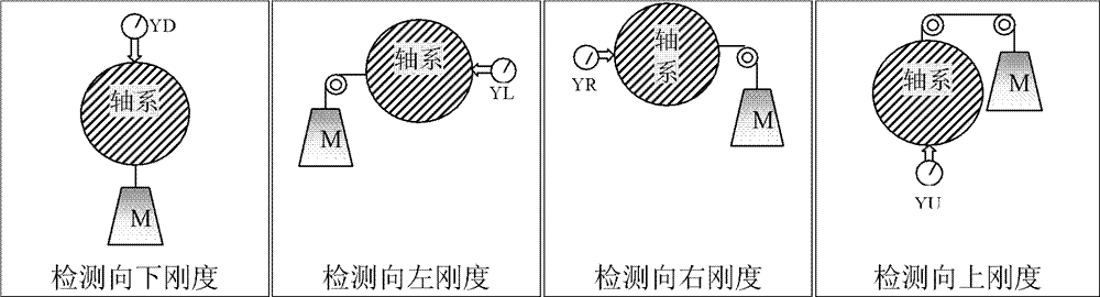
[0217] Example 1: Measurement of the low stiffness function of the machine 1 support.

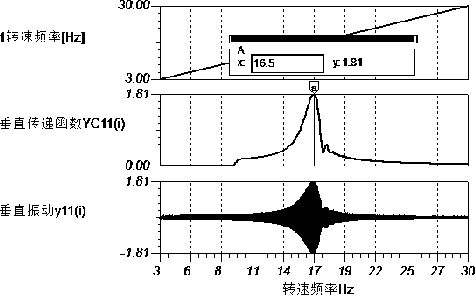
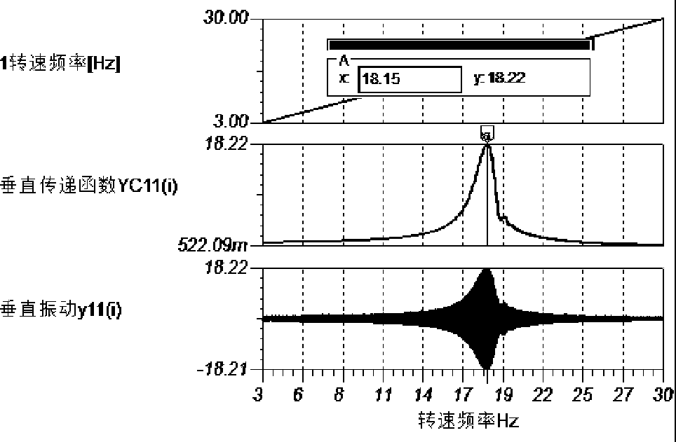
[0218] For N(0)~N(i), the vibration value of the first order at i+1 rotation speed is divided by the corresponding vibration value X11(0) and Y11(0) at the first lowest rotation speed to get the return A unified transfer function value containing (possibly multiple) resonance factors:

[0219] XC11(0~i)=X11(0~i) / X11(0), YC11(0~i)=Y11(0~i) / Y11(0),

[0220] Then divide the corresponding first-order vibration magnitude and second-order vibration magnitude by the above transfer function value to get the implicit, original vibration function that removes the (possibly multiple) resonance factors expressed by the transfer function value:

[0221] Original vibration function XG11(0~i), YG11(0~i),

[0222] Then, use the following formula to calculate the low-rigidity direction angle and the low-rigidity vibration value at different speeds Ni=N(0)~N(i):

[0223] The low stiffness vibration value of machine 1 ...

Embodiment 2

[0229] Example 2: Measurement of the misalignment function of machine 1

[0230] The support stiffness and misalignment dynamic test and diagnosis software contained in the computer 37 of the support stiffness and misalignment dynamic tester, through the vibration measurement of the machine from the low speed to the highest test speed, or from the low speed to the highest test speed. Several constant speed vibration measurements of N(0)~N(i) (i+1) quasi-full speed test speed data and their corresponding vibration data samples N(0~i) and x1(0~i) ), y1(0~i); analyze and process the above 2(i+1) vibration data samples separately, separate the horizontal and vertical first-order vibration of one of the machines, and obtain the first-order vibration magnitude of the quasi-full speed range: X11(0~i), Y11(0~i).

[0231] Analyze and process the above 2(i+1) vibration data samples separately, separate the horizontal and vertical second-order vibration of one of the machines, and obtain the...


PUM


Abstract

The invention discloses a testing method and an apparatus for a supporting state, a dynamic balancing state and a non-centering state of a rotating machine. The testing apparatus comprises a machine 1, a machine 2, and a shaft coupling. The testing apparatus is characterized in that: the machine 1 is connected with the machine 2 through the shaft coupling; a horizontal vibration sensor X1 and a vertical vibration sensor Y1 are installed on a casing and an engine base of the machine 1, wherein the casing and the engine base are at the side close to the shaft coupling; a horizontal vibration sensor X2 and a vertical vibration sensor Y2 are installed on a casing and an engine base of the machine 2, wherein the casing and the engine base are at the side close to the shaft coupling; a speed detection sensor N and a supporting stiffness and non-centering dynamic tester 3 are installed on the machine 1 and the machine 2. According to the traditional static detection method, there is a bind area in which a supporting stiffness state and a centering state can not be identified on the dynamic condition of the machine, so that debugging can not be guided comprehensively and correctly; however, according to the testing method and the apparatus, the above-mentioned problem can be solved.

Description

Technical field [0001] The invention relates to the technical field of reliability and safety of mechanical equipment, in particular to a method and device for testing the supporting state, dynamic balance and misalignment of a rotating machine. Background technique [0002] Modern complex machines are usually composed of several functional single machines combined through mechanical connections; rotating machines are composed of couplings. The common problem is: not only because each machine has its own independent support and the anisotropy of the static stiffness of the support, but also the equivalent static stiffness changes under the dynamic conditions of operation, and there is resonance after it is combined with the system , There are also static misalignment of each machine and dynamic misalignment which is different from static misalignment. As a result, the dynamic stiffness, damping and misalignment effects are different from the static effects when the system is ins...

Claims


Application Information

Patent Timeline
Patent Type & Authority Patents(China)
IPC IPC(8): G01M13/00G01M1/22G01B21/24
Inventor 唐德尧王智曾承志李合林
Owner 北京唐智科技发展有限公司
Why Eureka
Try Eureka