A test structure and test method for hot carrier effect of MOS device
A technology of MOS device and test structure, applied in the field of test structure of MOS device hot carrier effect, can solve problems such as low test efficiency, and achieve the effects of improving test efficiency, saving stress loading time, and improving test time
- Summary
- Abstract
- Description
- Claims
- Application Information
AI Technical Summary
Problems solved by technology
Method used
Image
Examples
Embodiment 1
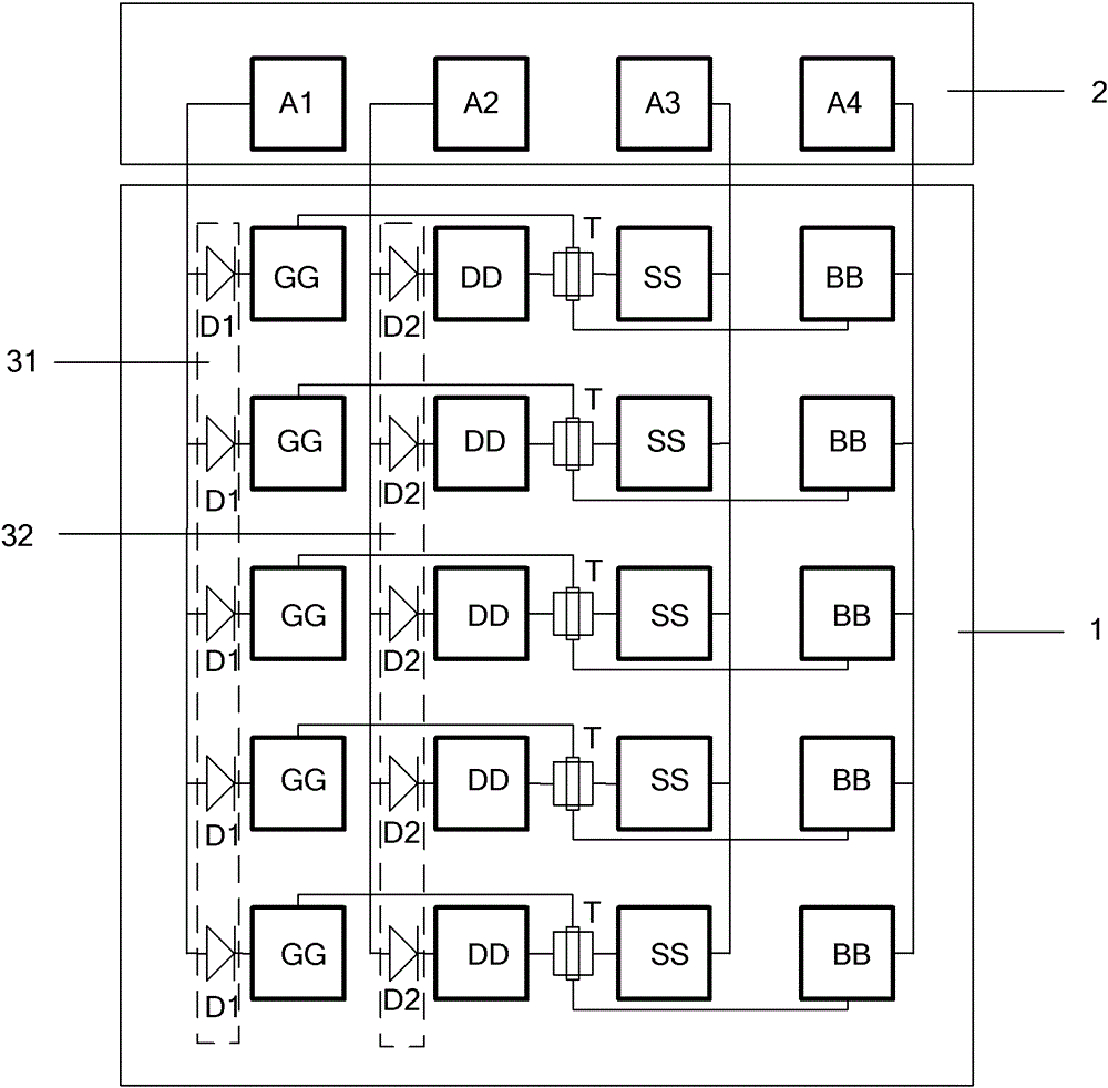
[0026] Such as figure 1 As shown, the test structure of the hot carrier effect of the MOS device of the present invention includes at least two groups of test structure units 1 of the array, and each group of test structure units 1 includes a gate terminal, a drain terminal, The source terminal, the gate pad GG electrically connected to the substrate, the drain pad DD, the source pad SS, and the substrate pad BB; the gate pad GG of each group of test structural units 1 passes through the first two The pole transistor D1 is reversely connected to the first pad A1, and the drain pad DD of each group of test structure units 1 is reversely connected to the second pad A2 through the second diode D2, and each group of test structure The source pad SS and the substrate pad BB of the cell 1 are connected to the third pad A3 and the fourth pad A4 respectively.
[0027] Wherein, the gate pad GG of each group of test structure units 1 is reversely connected to the first pad A1 through t...
Embodiment 2
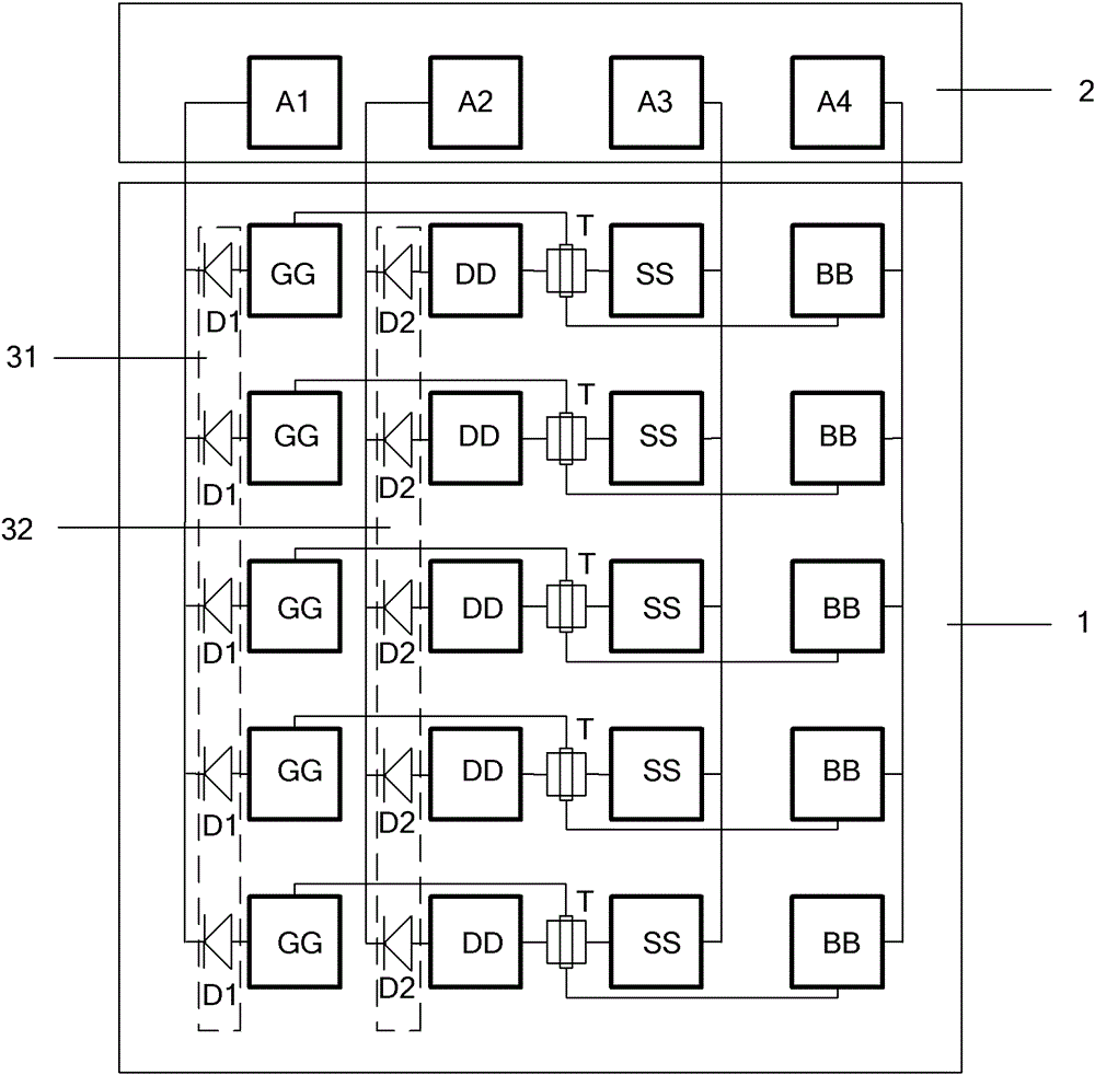
[0032] Such as figure 2 As shown, this embodiment 2 is improved on the basis of embodiment 1, and the difference is: the first diode connecting the gate pad GG of each group of test structure units 1 to the first pad A1 in reverse The tube D1 is changed to forward connection, and the second diode D2 reversely connected between the drain pad DD and the second pad A2 of each group of test structure units 1 is changed to forward connection. Wherein, the MOS device T is a P-type MOS device.
[0033] In Embodiment 2, after the gate pad GG is positively connected to the first pad A1 through the first diode D1, the voltage applied to the gate pad GG is a low level, and the drain pad DD is connected to the first pad A1 through the second diode D1. After the electrode transistor D2 is positively connected to the second pad A2, the voltage applied to the drain pad DD is low level. Therefore, this embodiment 2 is applicable to the hot carrier effect parameter test of the N-type MOS tra...
PUM
 Abstract
Description
Claims
Application Information
 - R&D
- Intellectual Property
- Life Sciences
- Materials
- Tech Scout
- Unparalleled Data Quality
- Higher Quality Content
- 60% Fewer Hallucinations
Browse by: Latest US Patents, China's latest patents, Technical Efficacy Thesaurus, Application Domain, Technology Topic, Popular Technical Reports.
© 2025 PatSnap. All rights reserved.Legal|Privacy policy|Modern Slavery Act Transparency Statement|Sitemap|About US| Contact US: help@patsnap.com


