Holder stay fixing structure and motor with brush

A support plate and structure technology, which is applied in the field of live brush motors, can solve problems such as support support plate damage, and achieve the effect of improving assembly workability and preventing damage

Active Publication Date: 2011-11-23
MITSUBA CORP
View PDF9 Cites 0 Cited by
  • Summary
  • Abstract
  • Description
  • Claims
  • Application Information

AI Technical Summary

Problems solved by technology

Therefore, if the shaft portion of the rivet is expanded in diameter in the rivet hole of the stent strut, the rivet hole of the stent strut will be squeezed and expanded radially outward, and there is a possibility that the stent strut will be damaged due to stress.

Method used


Image

  • Holder stay fixing structure and motor with brush
  • Holder stay fixing structure and motor with brush
  • Holder stay fixing structure and motor with brush

Examples


no. 1 approach

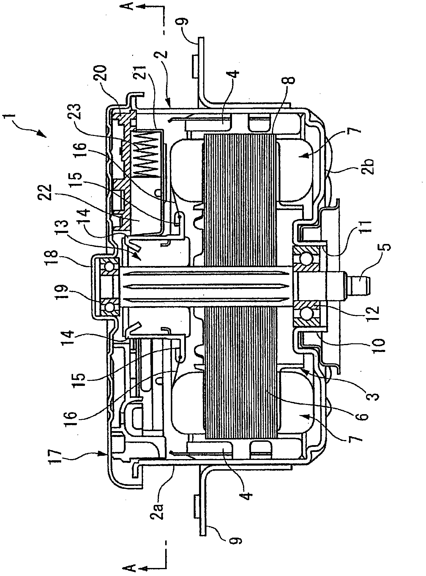
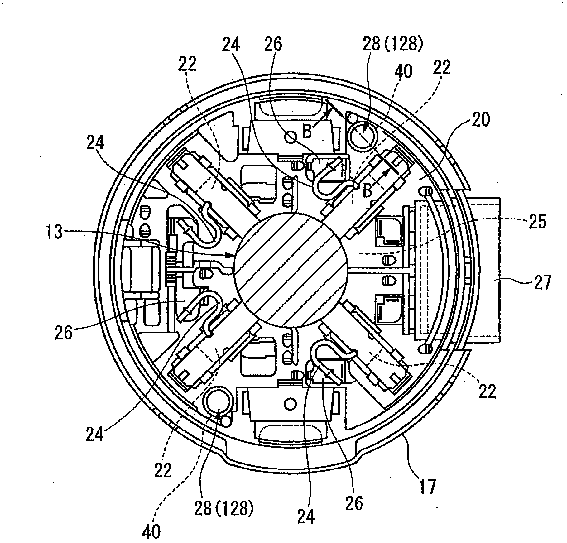
[0048] Such as figure 1 as well as figure 2 As shown, the brushed motor 1 is a driving source of an electric product (for example, a radiator fan) mounted on a vehicle. The brushed motor 1 has an armature 3 rotatably provided in a bottomed cylindrical yoke 2 , and an opening 2 c of the yoke 2 is closed by an end bracket 17 .

[0049] A support plate 9 used to fix the brushed motor 1 outside protrudes from the peripheral wall 2 a of the yoke 2 , while a plurality of permanent magnets 4 are juxtaposed along the peripheral direction inside the peripheral wall 2 a. In addition, a boss portion 10 is formed at an approximate center in the radial direction at an end portion (bottom portion) 2 b of the yoke portion 2 . In this boss portion 10 , an insertion hole 11 through which the rotating shaft 5 of the armature 3 is inserted is formed, and a bearing 12 for rotatably supporting one end side of the rotating shaft 5 is incorporated therein.

[0050] The armature 3 includes an arm...


PUM


Abstract

Provided is a holder stay fixing structure which is used for fixing a holder stay for supporting a brush slidingly contacting contact with a commutator to the end bracket of a motor with a brush by a rivet, a cylindrical part for receiving the part of the rivet having a diameter enlarged by its buckling deformation is formed in the end bracket at its portion through which the rivet is inserted. Consequently, the holder stay fixing structure capable of preventing the holder stay from being damaged during its assembling; and the motor with the brush can be provided.

Description

[0001] This application is a divisional application of an invention patent application titled "Bracket support plate fixing structure and live brush motor", the international filing date is February 19, 2008, and the application number is 200880005343.X. technical field [0002] The invention relates to a bracket support plate fixing structure and a live brush motor using the bracket support plate fixing structure. [0003] This case claims priority based on Japanese Patent Application No. 2007-38257 and Japanese Patent Application No. 2007-38258 filed in Japan on February 19, 2007, and the contents thereof are cited here. Background technique [0004] Conventionally, there is a brushed motor as a fan motor used for cooling a radiator of an automobile, for example. Such a brushed motor has a cylindrical yoke on which a plurality of permanent magnets are mounted on an inner peripheral surface, and a bracket closing an opening of the yoke, and an armature is rotatably supporte...

Claims


Application Information

Patent Timeline
Patent Type & Authority Applications(China)
IPC IPC(8): H02K5/14
CPCH02K5/148
Inventor 宫本保矶田稔细井启一
Owner MITSUBA CORP
Why Eureka
Try Eureka