Brake system of a rail vehicle with reduced stick-slip effect

A technology for braking equipment and rail vehicles, which is applied in the direction of brakes, brake components, vehicle components, etc., and can solve the problems of low material noise reduction, sticking and sliding, etc.

Active Publication Date: 2011-11-23
KNORR BREMSE SYST FUR SCHIENENFAHRZEUGE GMBH
View PDF4 Cites 9 Cited by
  • Summary
  • Abstract
  • Description
  • Claims
  • Application Information

AI Technical Summary

Problems solved by technology

This disturbing noise occurs especially in high-power brake equipment made of sintered metal, although it has very good braking performance, due to its tribol

Method used


Image

  • Brake system of a rail vehicle with reduced stick-slip effect
  • Brake system of a rail vehicle with reduced stick-slip effect
  • Brake system of a rail vehicle with reduced stick-slip effect

Examples


Embodiment Construction

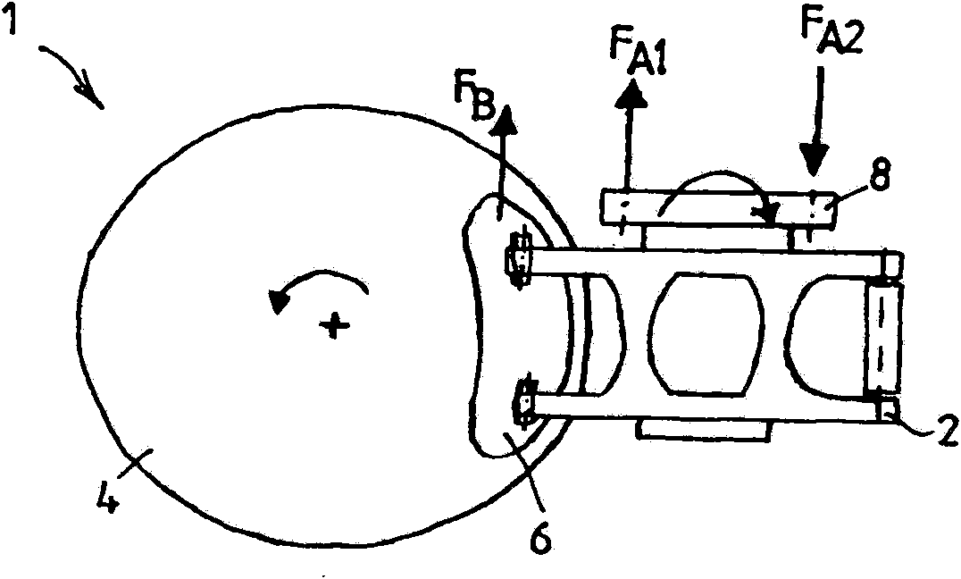
[0019] exist figure 1 A disc brake 1 for a rail vehicle according to a preferred embodiment of the invention is shown in , as is also known in principle, for example, from DE 102 45 207 C1 and is therefore only briefly described below.

[0020] The disc brake 1 comprises a brake caliper unit 2 as a brake actuator or brake application device, which has a service braking unit and an energy storage braking unit (not shown here). The brake caliper unit 2 comprises a brake disc 4 which cooperates with, for example, two brake linings 6 in a known manner, figure 1 Only one of the two brake linings is visible in the side view of the . The brake caliper unit 2 is preferably actuated pneumatically for generating a braking force F acting in the circumferential direction of the brake disc 4 according to the braking requirements B . Alternatively, it is of course also possible for the brake caliper unit 2 to be actuated with a pressure medium in another way, for example hydraulically or...


PUM


Abstract

The invention relates to a brake system (1) of a rail vehicle, having at least one brake actuator (2) comprising at least one brake disk (4) and at least one brake lining (6), which interacts with said brake disk (4), for generating a braking force in response to a braking demand. The invention provides at least one sensor device in order to measure at least one variable which represents jerky sliding motion, arising from the braking demand, between the brake disk (4) and the at least one friction lining (6), and to output a signal dependent on the measured variable to a control device which is designed so as to adapt the braking force generated by the brake actuator (2) as a function of a deviation of the measured variable from a predefined value or value range of the variable.

Description

technical field [0001] The invention relates to a braking system for a rail vehicle according to the preamble of claim 1, the braking system having at least one brake actuator comprising at least one brake disc and at least one brake Brake linings interacting with discs for generating a braking force according to braking requirements. The invention also relates to a method for controlling a braking system of a rail vehicle according to the preamble of claim 5 . Background technique [0002] A suitable brake system and a suitable method are known, for example, from DE 102 45 207 C1. In such braking equipment, when braking with a relatively small braking force, for example, when driving into a station with stop braking, a high-frequency sudden braking noise is usually generated, which is harmful to passengers and residents near the station. is particularly disturbing. This disturbing noise occurs especially in high-power brake equipment made of sintered metal, although it ha...

Claims


Application Information

Patent Timeline
IPC IPC(8): B60T8/00
CPCB60T8/00B60T17/228B60T13/665B60T8/52
Inventor 马尔科・诺克
Owner KNORR BREMSE SYST FUR SCHIENENFAHRZEUGE GMBH
Why Eureka
Try Eureka