
seat belt retractor

A winding device, a technology for seat belts, applied in the direction of belt tensioners, etc.

Active Publication Date: 2011-11-30
KK TOKAI RIKA DENKI SEISAKUSHO
View PDF6 Cites 7 Cited by
  • Summary
  • Abstract
  • Description
  • Claims
  • Application Information

AI Technical Summary

Problems solved by technology

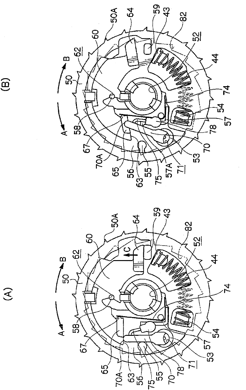
Therefore, it is necessary to provide a space for the hook of the lever to displace from the locking groove of the inertial mass toward the radially outer side of the V-gear, and to increase the size of the V-gear.

Method used


Image

  • seat belt retractor
  • seat belt retractor
  • seat belt retractor

Examples


Embodiment Construction

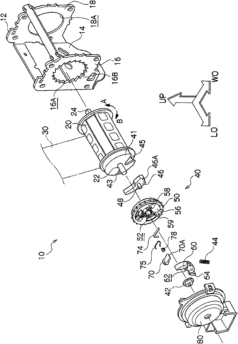
[0026] figure 2 The overall structure of the seat belt take-up device 10 according to the embodiment of the present invention is shown in an exploded perspective view. In addition, in the drawings, one side in the vehicle front-rear direction is indicated by an arrow LO, one side in the vehicle width direction is indicated by an arrow WO, and the vehicle upper direction is indicated by an arrow UP.

[0027] Such as figure 2 As shown, the belt retractor 10 has a frame 12 . The frame 12 is composed of a substantially plate-shaped back plate 14, a leg plate 16 and a leg plate 18 extending integrally from both ends of the back plate 14 in the width direction, and the back plate 14 is attached to the vehicle body by a fastening mechanism not shown such as a bolt , so that the seat belt take-up device is installed on the vehicle body. Circular arrangement holes 16A and 18A are respectively formed through the leg plate 16 and the leg plate 18 , and ratchet teeth 16B (internal te...


PUM


Abstract

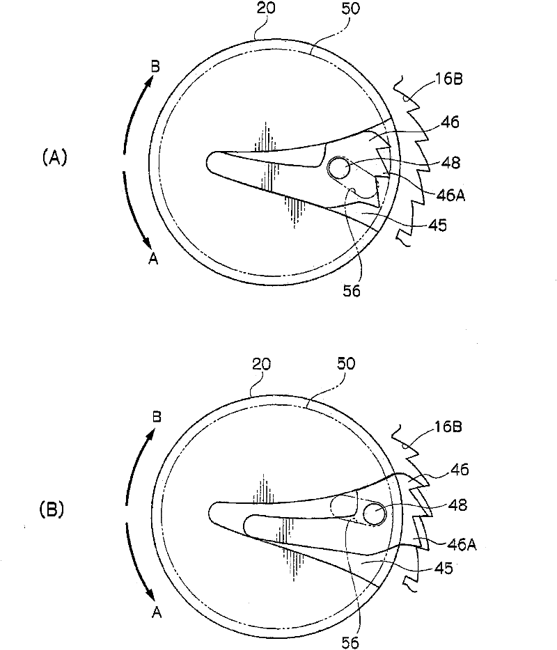
The invention aims at providing a webbing retractor capable of realizing miniaturization of a rotation body. Wherein, a V-shaped gear is connected at a spool in a mode of capability of rotation with the spool, pawls ELF are disposed at the V-shaped gear. When the V-shaped gear rotates in the pulled-out direction and a W paw is relatively displaced with respect to the V-shaped gear, a lock piece limits rotation of the spool in the pulled-out direction. Additionally, via rotation of the V-shaped gear in a retraction direction, an engaging portion of ratchet teeth is engaged with the W pawl, and the pawls limit displacing of the W pawl with respective to the V-shaped gear caused by resulting from rebound of the stopping of the retraction of the webbing. Herein, due to rotation of the V-shaped gear in the pulled-out direction, the engagement of the engaging portion with the W pawl is released as the engaging portion is displaced toward a radial direction inside of the V-shaped gear. Therefore, miniaturization of the V-shaped gear can be realized without disposing of a space for displacement of the engagement portion at the engagement position of the W pawl and the engagement portion toward the radial external side of the V-shaped gear.

Description

technical field [0001] The present invention relates to a seat belt winding device for winding a seat belt fastened to a vehicle occupant. Background technique [0002] In the seat belt take-up device shown in the third embodiment of Patent Document 1 below, the V-shaped gear is rotatable following the reel, and the rod and the inertial mass are supported by the V-shaped gear. One end of the inertia block is provided with a locking groove, and the hook of the rod can engage with the locking groove from the radially outer side of the V-shaped gear. [0003] When the seat belt is pulled out from the spool rapidly, the V-shaped gear rotates following the spool, and the lever rotates in the pulling direction, thereby rotating the lever radially outward of the V-shaped gear. As a result, the hook of the rod is separated from the locking groove of the inertial mass, and the inertial mass (including centrifugal force) relatively swings relative to the V-shaped gear. [0004] On t...

Claims


Application Information

Patent Timeline
IPC IPC(8): B60R22/38B60R22/41
CPCB60R22/38B60R22/41B60R22/34B60R22/46
Inventor 立间笃角屋敷晃
Owner KK TOKAI RIKA DENKI SEISAKUSHO
Learn More