Method and device for coordinated multi-point transmission
A multi-point coordination and transmission method technology, applied in the field of communication, can solve the problem that multiple cells cannot schedule cooperative users, and achieve the effect of realizing forward compatibility and improving system throughput and spectrum efficiency
- Summary
- Abstract
- Description
- Claims
- Application Information
AI Technical Summary
Problems solved by technology
Method used
Image
Examples
example 1
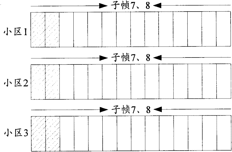
[0071] In this embodiment, the special unicast time unit is an MBSFN subframe, and a fixed number of OFDM symbols are configured for the PDCCH in the MBSFN subframe, or reconfigured on the basis of the number of OFDM symbols configured for the PDCCH in the MBSFN subframe in R8 A fixed number of OFDM symbols are used for PDCCH mapping. The manner of configuring OFDM symbols for the PDCCH in the MBSFN subframe adopts a static or semi-static configuration manner.
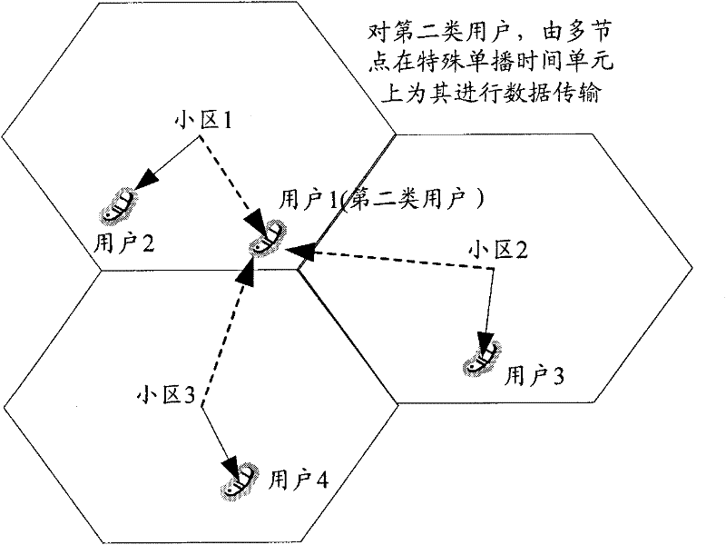
[0072] like figure 1 As shown, the serving cell of users 1 and 2 is cell 1, the serving cell of user 3 is cell 2, and the serving cell of user 4 is cell 3. User 1 is the second type of user, and cells 1, 2, and 3 form a cooperative set for joint processing. Users 2, 3, and 4 are all users of the first type, and are non-cooperative users in the first type of users.
[0073] For the first type of users 2, 3, and 4, they are independently scheduled by the serving cells to which they belong. For the second type of user...
example 2
[0079] In this embodiment, the special unicast time unit is an MBSFN subframe. The manner of configuring OFDM symbols for the PDCCH in the MBSFN subframe adopts a static or semi-static configuration manner.
[0080] like Figure 4As shown, the serving cell of users 1 and 4 is cell 1, the serving cell of user 2 is cell 2, and the serving cell of user 3 is cell 3. User 1 is the second type of user, and cells 1, 2, and 3 form a cooperative set for joint processing. User 2 is a first-type user, and is a CS / CB cooperative user among the first-type users, and is coordinated and scheduled by cells 2 and 3 . Users 3 and 4 are R8 users in the first type of users, that is, non-cooperative users.
[0081] For the second type of user 1, a cooperative set including cells 1, 2, and 3 performs joint scheduling and joint transmission. For the first type of user 2, joint scheduling is performed by the cooperative set including cell 2 and cell 3, and the serving cell (cell 2) transmits it i...
example 3
[0086] Such as Figure 5 As shown, the serving cell of users 1 and 2 is cell 1, the serving cell of user 3 is cell 2, and the serving cell of user 4 is cell 3. There is no second type of user in the system, user 1 is a CS / CB cooperative user in the first type of user, and the serving cell (cell 1), cell 2, and cell 3 form a cooperative set to coordinate scheduling. Users 2, 3, and 4 are all R8 users in the first type of users, that is, non-cooperative users.
[0087] Because there is no second type of user, the MBSFN subframe in this system does not need to carry joint processing data, and is only used to transmit MBMS services.
[0088] For the first type of user 1, the cooperative set including cells 1, 2, and 3 performs joint scheduling, and cell 1 performs independent transmission and joint transmission. For the first type of users 2, 3, and 4, they are independently scheduled and transmitted by their respective serving cells.
[0089] The subframe configuration of the ...
PUM
 Abstract
Description
Claims
Application Information
 - R&D
- Intellectual Property
- Life Sciences
- Materials
- Tech Scout
- Unparalleled Data Quality
- Higher Quality Content
- 60% Fewer Hallucinations
Browse by: Latest US Patents, China's latest patents, Technical Efficacy Thesaurus, Application Domain, Technology Topic, Popular Technical Reports.
© 2025 PatSnap. All rights reserved.Legal|Privacy policy|Modern Slavery Act Transparency Statement|Sitemap|About US| Contact US: help@patsnap.com


