Valve units for pressure vessels

A pressure vessel, valve unit technology, applied in pressure cookers, applications, cooking utensils, etc., can solve problems such as unacceptable

Active Publication Date: 2011-11-30
菲仕乐有限公司
View PDF10 Cites 3 Cited by
  • Summary
  • Abstract
  • Description
  • Claims
  • Application Information

AI Technical Summary

Problems solved by technology

The user also cannot receive any visual information through the pin indicator that the pressure in the container is too high; he can only see the vapor appearing when the valve responds

Method used


Image

  • Valve units for pressure vessels
  • Valve units for pressure vessels

Examples


Embodiment Construction

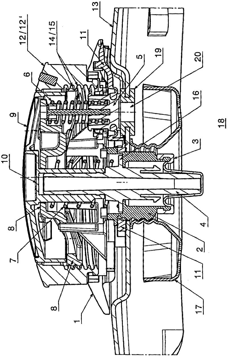
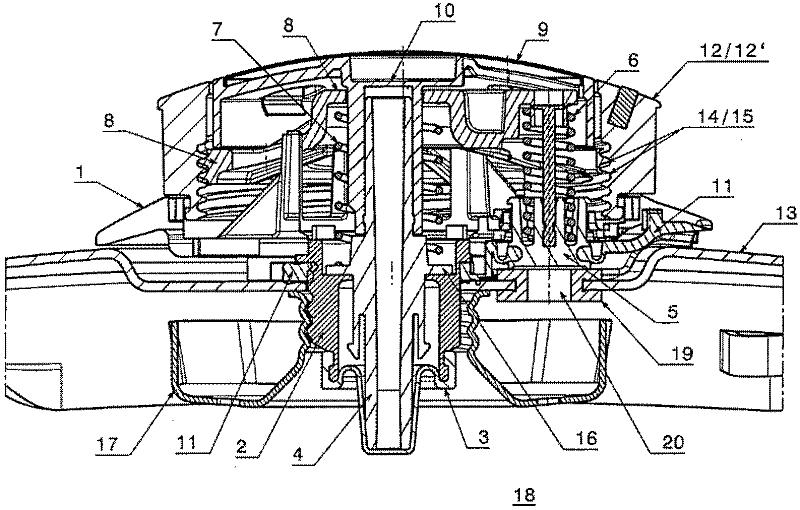
[0019] The valve unit according to the invention has a carrier plate 1 equipped with profiled seals 11 which carries all the valve components and can be fitted in the opening of a cover 13 which can be placed on the receiver of a pressure vessel to make the pressure vessel pressure-tight, in which case said carrier plate 1 can be held in place by means of retaining nuts 17 and via a rolling-membrane seat member 2 through which protrudes through the opening and is provided with external threads.

[0020] The valve unit has an axially movable indicator pin 4 formed, for example, as a sleeve member, on a part of said indicator pin 4 exposed from the top of the valve housing 12 during pressurization or On the part cooperating with the indicator piston 10 bears a circular marking which, for example, provides the user with information about the pressure situation in the container interior 18 . The indicator pin 4 is supported by a so-called rolling membrane 3 which transmits the pr...


PUM


Abstract

The invention relates to a valve unit for a pressure vessel, the latter consisting of a receptacle and a lid which can be placed on said receptacle in such a way as to make it pressure-tight and said valve unit including: a safety function, pressure-relief function and pressure indicator function; adjustable indicator levels and pressure levels; an indicator pin (4) or indicator piston (10) which is supported against an indicator spring (7), can move in axial direction and bears on its portion becoming visible upon pressurization, due to its emergence from a valve housing (12), indicator rings, for example, for indicating the pressure inside the vessel; and comprising a valve body (5) which is movable in axial direction against the action of an exhaust steam spring (6) and, in the closed position, rests against a seal seat (19), lifting off from this, when a given pressure inside the vessel is exceeded, to uncover a pressure-relief aperture (20), in which case both the indicator spring (7) and the exhaust steam spring (6) are braced in the same direction against a common, axially adjustable pressure member (8).

Description

technical field [0001] The invention relates to a valve unit for a pressure vessel consisting of a receptacle and a cover intended to be placed on said receptacle in such a manner that said receptacle is pressure-tight, said valve unit comprising : safety function, pressure relief function and pressure indicator function; indicator level and pressure level that can be adjusted; indicator pin or indicator piston supported on the indicator spring, which can be adjusted in the axial direction direction and carries on a part thereof, for example, an annular indicator area for indicating the pressure inside the container, said part becoming visible when pressurized due to said part emerging from the valve housing; And the valve unit includes a valve body, the valve body can move axially against the action of the exhaust spring, and in the closed position, the valve body rests on the sealing seat, and when the given pressure inside the container is exceeded When , the valve body ri...

Claims


Application Information

Patent Timeline
Patent Type & Authority Applications(China)
IPC IPC(8): A47J27/09
CPCA47J27/09Y10T137/8326A47J27/092
Inventor A·特伦J·尼夫H·米勒B·海德里希
Owner 菲仕乐有限公司
Why Eureka
Try Eureka