Posture compensation method in case of mismatched side-swing push-broom velocity in imaging of agile satellite

A compensation method and satellite technology, applied in the field of attitude compensation, can solve problems such as small imaging range, inability to cover regional targets, and small imaging width of spaceborne remote sensors

Active Publication Date: 2013-05-01
AEROSPACE DONGFANGHONG SATELLITE
View PDF6 Cites 0 Cited by
  • Summary
  • Abstract
  • Description
  • Claims
  • Application Information

AI Technical Summary

Problems solved by technology

[0004] (1) In the imaging mode mentioned in the article, the imaging width of the spaceborne remote sensor is small, and the imaging range is small, usually a small circular or rectangular area, which cannot effectively cover the regional target. The imaging task is single; the attitude compensation technology in the above mode is based on the drift angle attitude control when the attitude is fixed to the ground pointing, but the drift angle attitude compensation technology under the condition that the attitude is constantly changing to the ground pointing during satellite side-swing push-broom imaging has not yet been implemented. give specific measures
[0005] (2) In this paper, it is assumed that the moving speed of the sub-satellite point matches the surface push-broom speed of the camera, and the attitude compensation of the drift angle only considers the drift angle caused by the rotation of the earth, and the attitude compensation has great limitations: in the above mode The attitude compensation method is only suitable for the case where the moving speed of the sub-satellite point is consistent with the speed of the camera push-broom, that is, the situation where the satellite is pushing-broom along the orbit, and cannot meet the situation when the moving speed of the sub-satellite point of the agile satellite does not match the speed of the camera push-broom
The satellite attitude compensation method based on the drift angle in the traditional mode (the moving speed of the sub-satellite point is consistent with the camera push-broom speed) can no longer meet the attitude adjustment requirements of agile satellite imaging

Method used


Image

  • Posture compensation method in case of mismatched side-swing push-broom velocity in imaging of agile satellite
  • Posture compensation method in case of mismatched side-swing push-broom velocity in imaging of agile satellite
  • Posture compensation method in case of mismatched side-swing push-broom velocity in imaging of agile satellite

Examples


Embodiment Construction

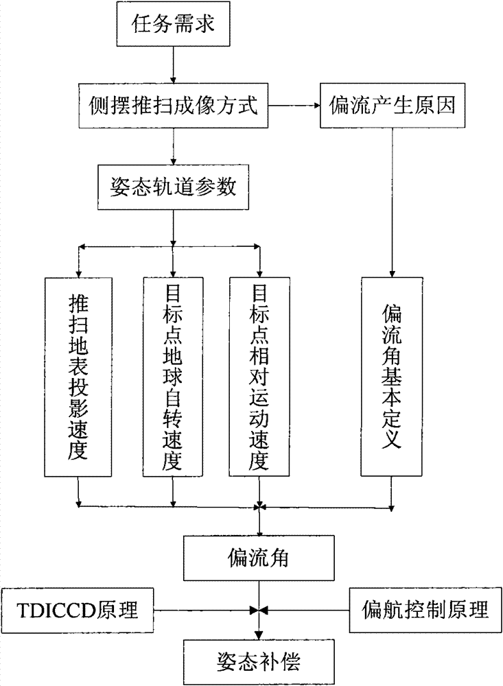
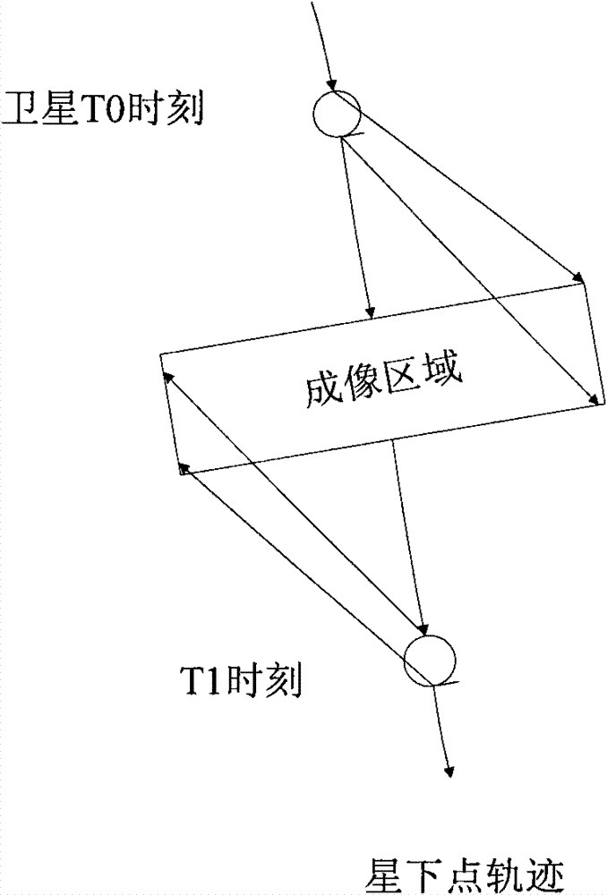
[0041] Such as figure 1 Shown is the flowchart of the method of the present invention. The method of the present invention mainly includes two parts: calculating the drift angle in the push-broom mode perpendicular to the track direction of the sub-satellite point, and the yaw control and compensation of the attitude.

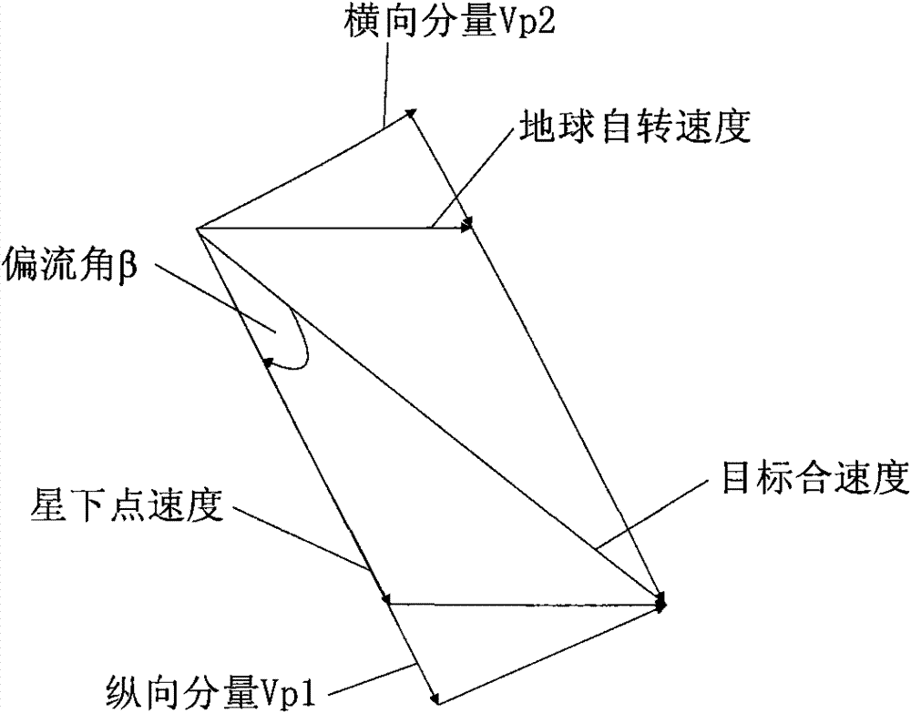
[0042] The essence of the drift angle is the angle between the camera push-broom direction and the target speed direction. The calculation process of the drift angle is as follows:

[0043] (1) Determine the projected velocity of the camera’s push-broom velocity on the surface, the linear velocity of the earth’s rotation at the target point, and the relative moving linear velocity of the target point caused by orbital motion in the east-west pendulum push-broom imaging mode;

[0044] (2) Analyze the cause of the target point closing speed to obtain the target point closing speed;

[0045] (3) Deduce the longitudinal component of the target point-joint velocit...


PUM


Abstract

The invention discloses a posture compensation method in case of mismatched side-swing push-broom velocity in imaging of an agile satellite. For the limitation (only the drift action caused by auto-rotation of the earth is considered) of the posture compensation method in the traditional imaging mode (the pointing direction of the satellite to the ground is fixed), the drift angle calculation formula is obtained under the mode according to the track posture parameter by analyzing the reason for the generation of the drift angle under the imaging mode (namely the condition that the substellar point velocity is mismatched with the push-broom velocity of a camera, and the pointing direction of the posture at the moment to the earth changes continuously) that the pointing direction of the side-swing push-broom posture of the satellite to the earth changes continuously, considering the drift action of the imaging from the three aspects such as orbital motion, auto-rotation of the earth andthe push-broom velocity of a camera and combining the basic definition of the drift angle. On the basis, by combination of the basic principle of TDICCD (time delay integration charged coupling device) imaging and the yawing control principle, the satellite posture compensation method is given, so that the imaging requirement for side-swing push and broom of the agile satellite can be met.

Description

technical field [0001] The invention relates to an attitude compensation method for agile satellite imaging. Background technique [0002] During the imaging process of optical remote sensing satellites, there will be a certain deviation between the target imaging point and the actual imaging point due to factors such as orbital movement, earth rotation, attitude maneuvering, and camera working push-broom mode. measure. [0003] For the sub-satellite point imaging mode, the calculation formula of the drift angle has been mature; for the deviation from the sub-satellite point imaging mode, in "Calculation and Compensation of the Drift Angle of Spaceborne TDI-CCD Push-broom Camera" (Shanghai Aerospace Science and Technology, 6th issue of 2006) In this paper, Yuan Xiaokang deeply deduced the formula for calculating the drift angle of the camera during azimuth offset and elevation offset imaging, and proposed a method of using satellite yaw control to compensate the camera drif...

Claims


Application Information

Patent Timeline
Patent Type & Authority Patents(China)
IPC IPC(8): B64G1/24
Inventor 黄群东杨芳
Owner AEROSPACE DONGFANGHONG SATELLITE
Why Eureka
Try Eureka