
A heating system that uses heat pump technology to improve the heating capacity of central heating pipe networks

A technology of central heating and heating capacity, applied in hot water central heating systems, heating systems, household heating, etc., can solve the problems of waste of pipe network facilities, huge investment in heating pipe network, and inability to continue to improve, etc. achieve the effect of heating

Active Publication Date: 2011-12-07
TSINGHUA UNIV +1
View PDF3 Cites 40 Cited by
  • Summary
  • Abstract
  • Description
  • Claims
  • Application Information

AI Technical Summary

Problems solved by technology

[0003] On the one hand, the construction period of re-laying the heating pipe network is long, and the existing roads and municipal facilities in the city need to be destroyed, which will inevitably affect urban traffic and normal life. Moreover, the investment in the new heating pipe network is huge, and it also causes waste of the original pipe network facilities, etc. On the other hand, at present, the supply and return water temperatures of the urban central heating primary network are generally 120-65°C, and the water supply temperature of the primary network is limited by factors such as pipeline insulation, materials, safety, and heating sources, and cannot continue to increase. For conventional heat network heat exchangers, the return water temperature of the primary network is higher than that of the secondary network. Due to the limitation of the heat requirements of the secondary network, the return water temperature of the primary network cannot continue to decrease

Method used


Image

  • A heating system that uses heat pump technology to improve the heating capacity of central heating pipe networks
  • A heating system that uses heat pump technology to improve the heating capacity of central heating pipe networks
  • A heating system that uses heat pump technology to improve the heating capacity of central heating pipe networks

Examples


Embodiment 1

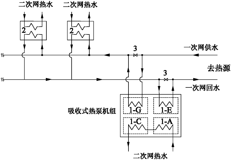
[0018] Embodiment 1: as figure 1 As shown, an absorption heat pump unit is installed near the heat source in the primary network of the central heating pipe network. The heating pipe network is a dendritic heat network, and the water supply pipeline of the primary network is connected to the generator 1-G of the absorption heat pump unit through pipes. , the primary network water supply is used as the driving heat source of the heat pump; the primary network return water pipeline is connected to the evaporator 1-E of the absorption heat pump unit through the pipeline, and the primary network return water is used as the low-temperature heat source; the secondary network return water pipeline passes through the pipeline and absorbs The hot water input end of the absorber 1-A of the absorption heat pump unit is connected, the water supply pipeline of the secondary network is connected with the hot water output end of the condenser 1-C of the absorption heat pump unit through pipes...

Embodiment 2

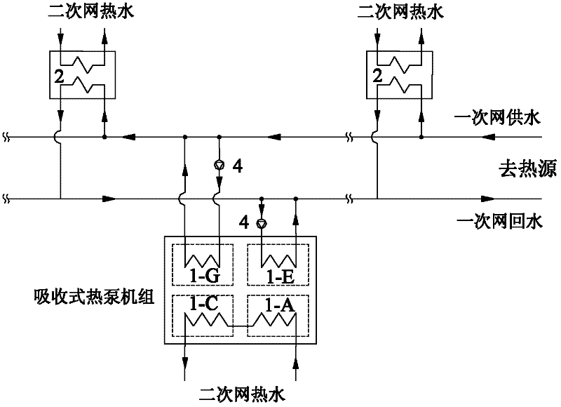
[0021] Embodiment 2: as figure 2 As shown, an absorption heat pump unit is installed in a certain section in the middle of the central heating primary network, the heating pipe network is a dendritic heat network, and the water supply pipeline of the primary network is connected to the generator 1-G of the absorption heat pump unit through pipelines , the primary network water supply is used as the driving heat source of the heat pump; the primary network return water pipeline is connected to the evaporator 1-E of the absorption heat pump unit through the pipeline, and the primary network return water is used as the low-temperature heat source; the secondary network return water pipeline passes through the pipeline and absorbs The hot water input end of the absorber 1-A of the absorption heat pump unit is connected, the water supply pipeline of the secondary network is connected with the hot water output end of the condenser 1-C of the absorption heat pump unit through pipes, ...

Embodiment 3

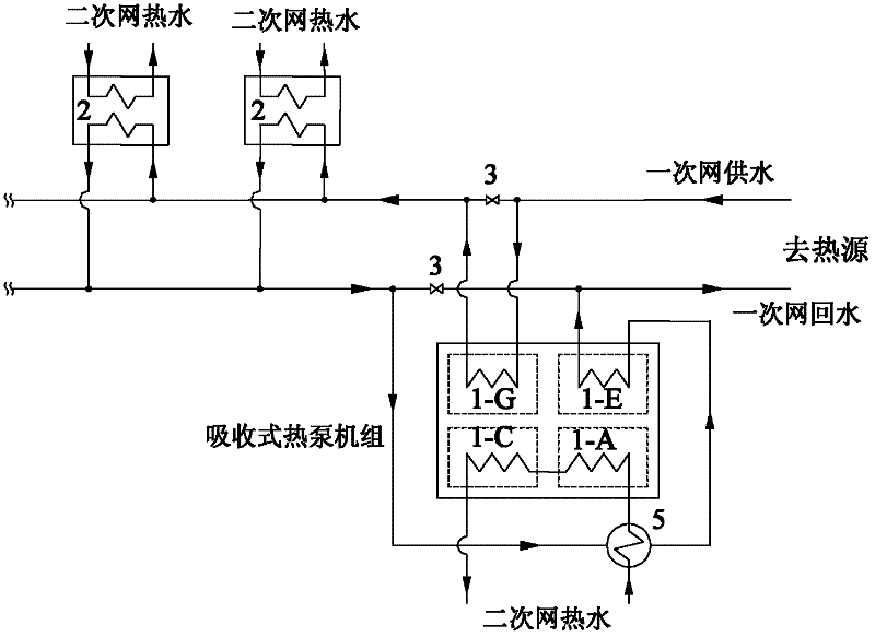
[0026] Embodiment 3: as image 3 As shown, the absorption heat pump unit is installed in the primary network of central heating, and the water supply pipeline of the primary network is connected with the generator 1-G of the absorption heat pump unit through the pipeline, and the water supply of the primary network is used as the driving heat source of the heat pump; the primary network returns The water pipeline is connected to the evaporator 1-E of the absorption heat pump unit through pipelines, and the return water of the primary network is used as a low-temperature heat source; the return water pipeline of the secondary network is connected to the hot water input end of the absorber 1-A of the absorption heat pump unit through pipelines The secondary network water supply pipeline is connected to the hot water output end of the condenser 1-C of the absorption heat pump unit through pipes, and the return water of the secondary network enters the absorber 1-A and the condense...


PUM


Abstract

The invention discloses a heating system utilizing a heat pump technology to improve the heat capacity of a central heating pipe network and belongs to the field of central heating. The heating system provided by the invention comprises the central heating pipe network, wherein the central heating pipe network is divided into a primary net and a secondary net; the heating system also comprises anabsorption heat pump set, a primary net water supply pipeline is connected with the generator of the absorption heat pump set by virtue of a pipeline, and the primary water supply is taken as the driving heat source of the absorption heat pump; a primary net return pipe is connected with the evaporator of the absorption heat pump set by virtue of a pipeline, and a primary net backwater is taken as the lower-temperature heat source of the absorption heat pump set; and a secondary net backwater enters into the absorber and condenser of the absorption heat pump set in turn so as to be heated, warmed and then output as a secondary water supply. The heating system provided by the invention has the advantages of further increasing the temperature difference of the water supply and backwater of the primary net, and improving the heat transfer capability of the heating pipe net.

Description

technical field [0001] The invention belongs to the field of central heating, and in particular relates to a heating system which utilizes heat pump technology to improve the heating capacity of a central heating pipe network. Background technique [0002] With the rapid development of China's urbanization process, the scale of urban central heating continues to expand, and the heating load within the radiation range of the existing central heating pipe network continues to increase. The central heating pipe network has or will soon face the problem of insufficient transmission capacity. , There are two ways to solve it: one is to re-lay large-scale heating network pipes, and the other is to further increase the temperature difference between the supply and return water of the primary network hot water, and improve the heat transfer capacity of the existing heating pipe network. [0003] On the one hand, the construction period of re-laying the heating pipe network is long, ...

Claims


Application Information

Patent Timeline
Patent Type & Authority Applications(China)
IPC IPC(8): F24D3/18F24D3/02
CPCY02B30/12
Inventor 付林张世钢罗勇肖常磊姜云涛
Owner TSINGHUA UNIV
Learn More