
Fast Edge Routing for Interactive Mapping

A routing, fast technology, applied in the field of interactive mapping, which can solve problems such as slow computational overhead

Active Publication Date: 2011-12-14
MICROSOFT TECH LICENSING LLC
View PDF2 Cites 6 Cited by
  • Summary
  • Abstract
  • Description
  • Claims
  • Application Information

AI Technical Summary

Problems solved by technology

For graphs with hundreds of nodes, the (number of nodes) quadratic or worse computational overhead to construct a visibility graph can be prohibitively slow, especially for interactive applications where the layout changes significantly from iteration to iteration. Word

Method used


Image

  • Fast Edge Routing for Interactive Mapping
  • Fast Edge Routing for Interactive Mapping
  • Fast Edge Routing for Interactive Mapping

Examples


Embodiment Construction

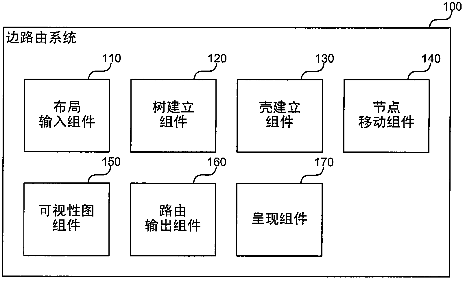
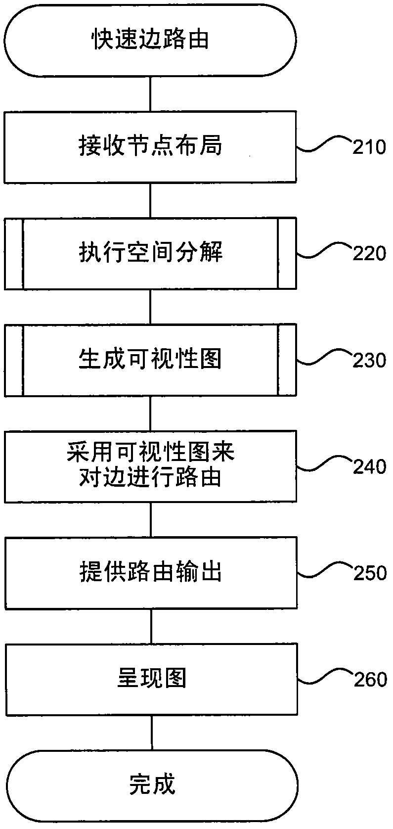
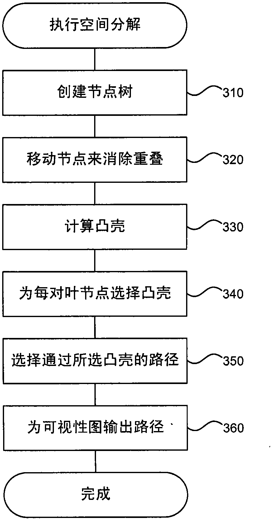
[0015] An edge routing system using spatial decomposition for faster routing and a cone generator for faster generation of sparse visibility graphs is described here. The system provides two approaches that use approximate shortest paths that can be used alone or in combination to achieve faster and thus more scalable and interactive edge routing. The first method uses a spatial decomposition of the nodes in the graph, shifting them slightly to get strictly disjointed convex hulls around groups of nodes, and then computing the visibility graph over these resulting shells rather than individual nodes. The second method generates a sparse visibility map generator to speed up the process of generating visibility maps. These two technologies are complementary, i.e. they can be used together for faster routing. Prior to this, high-quality edge routing for obstacle avoidance was not considered for use in large graphs (with hundreds or thousands of nodes) or for interactive mapping ...


PUM


Abstract

An edge routing system is described herein that uses a spatial decomposition to achieve faster routing, and more quickly generates a sparse visibility graph using a cone spanner. The system provides two approaches that can be used separately or in combination to achieve faster-and hence more scalable and more interactive-edge routing using approximate shortest paths. The first approach uses a spatial decomposition of the nodes in a graph, moving them slightly to obtain strictly disjoint convex hulls around groups of nodes, and then computing visibility graphs over these composite hulls rather than individual nodes. The second approach generates a sparse visibility-graph spanner to accelerate the process of producing the visibility graph. The system allows high quality obstacle avoiding edge routing for large diagrams in interactive diagramming applications where very fast refreshes of routing are used with many nodes moving at the same time.

Description

technical field [0001] The present invention relates to interactive mapping and in particular to edge routing systems that use spatial decomposition for faster routing and employ cone generators for faster generation of sparse visibility graphs. Background technique [0002] Most network diagrams (graphs) that people use to visualize various concepts have nodes associated with textual or graphical content. For example, in a Unified Modeling Language (UML) class diagram, nodes are drawn as boxes with textual content describing class properties or methods. As another example, in a metabolic pathway diagram, nodes representing chemical constituents have longer textual labels or graphical representations of molecular structures. [0003] A route is the path a connector takes to connect nodes. Labels may be obscured if no edges (connectors) directly connected to a particular node are drawn over that node. Alternatively, if an edge is drawn behind a node, the reader may incorre...

Claims


Application Information

Patent Timeline
Patent Type & Authority Applications(China)
IPC IPC(8): G06F17/30
CPCG06T11/206G06F17/30G06T11/00
Inventor T·G·杜耶L·纳克曼松
Owner MICROSOFT TECH LICENSING LLC
Learn More