
Transmission mechanism for valve of switch cabinet

A transmission mechanism and cabinet work technology, applied in the direction of switchgear components, etc., can solve the problem of reducing the effective transmission displacement of the transmission mechanism, the small travel of the handcart of the central circuit breaker, and the small distance between the contact arm of the handcart and the contact box, etc. problem, to achieve the effect of high fixing strength, small transmission error, and prevention of left and right sliding

Active Publication Date: 2013-09-25
SHANDONG TAIKAI COMPLETE ELECTRIC APPLIANCE
View PDF6 Cites 0 Cited by
  • Summary
  • Abstract
  • Description
  • Claims
  • Application Information

AI Technical Summary

Problems solved by technology

[0004] 1. The handcart stroke of the center-mounted circuit breaker is small, the valve drive is an arc-shaped chute, and the effective displacement is small; it is difficult for the conventional valve transmission mechanism to amplify the variable to the degree of opening and closing the valve, and the transmission error is large
[0005] 2. The distance between the contact arm of the handcart and the contact box of the center-mounted circuit breaker is small, and the valve transmission mechanism is required to provide sufficient displacement to make the valve respond when the handcart makes a small displacement. Otherwise, the contact arm of the handcart and the contact box will appear. The collision of the valve panels will cause the deformation of the valve panels and pose a safety hazard
[0006] 3. The conventional transmission mechanism is only fixed to one side of the side wall of the cabinet body. The transmission mechanism is prone to deformation when it is stressed, which reduces the effective transmission displacement of the transmission mechanism, resulting in the valve not being able to open or close smoothly.

Method used


Image

  • Transmission mechanism for valve of switch cabinet

Examples


Embodiment Construction

[0012] The present invention will be further described below in conjunction with accompanying drawing:

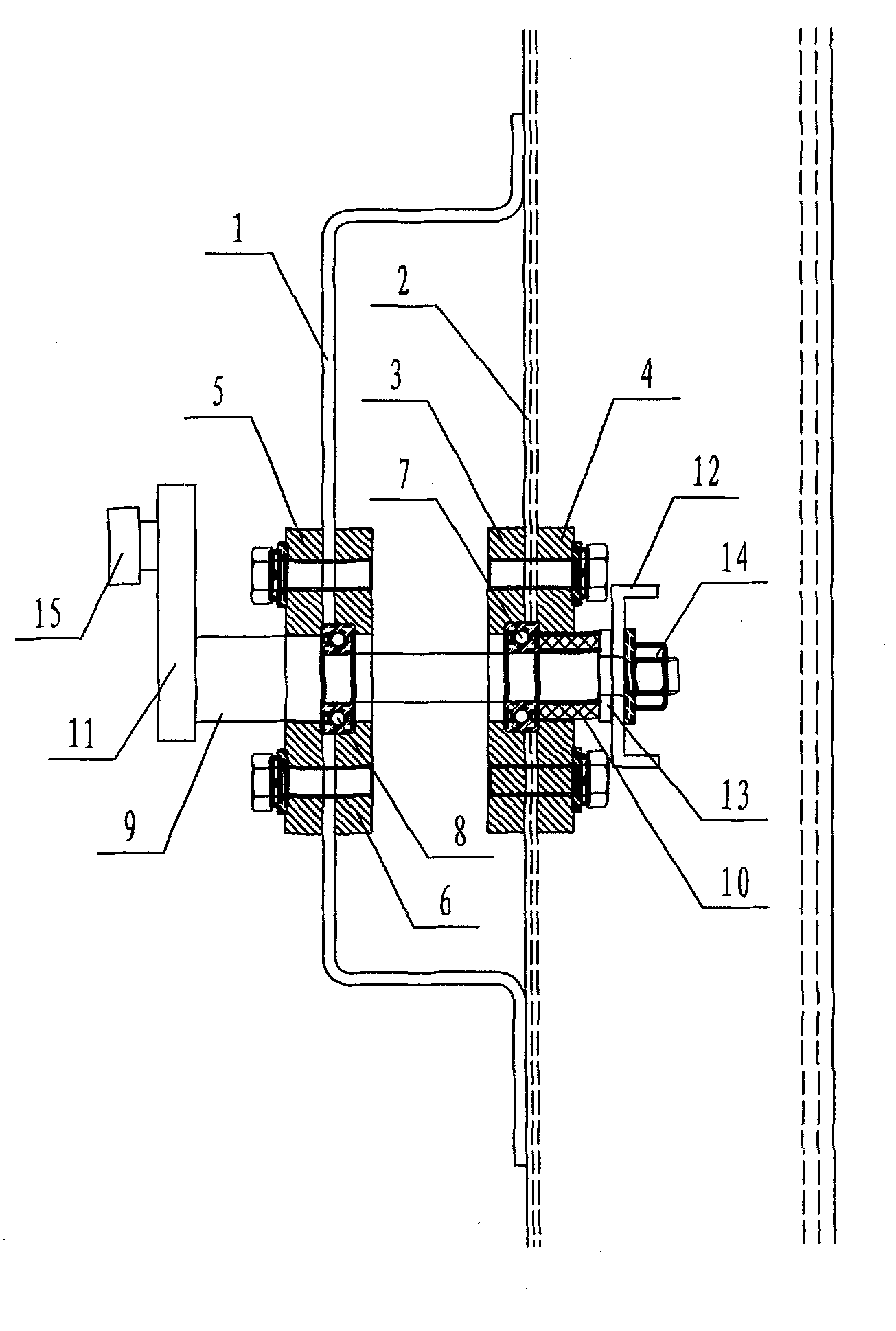
[0013] As shown in the figure, the handcart guide rail 1 is fixed on the left side of the side wall 2 of the cabinet body, and there is a certain distance between them. The bearing fixing plate I3 and the bearing baffle plate I4 are respectively fixed on the left and right sides of the side wall 2 of the cabinet body. The bearing baffle plate II5 and the bearing fixing plate II6 are respectively fixed on the left and right sides of the handcart guide rail 1. The bearing baffle II5, the handcart guide rail 1, the bearing fixing plate II6, the bearing fixing plate I3, the cabinet side wall 2 and the bearing baffle I4 are respectively provided with round holes through which the transmission shaft 9 passes sequentially, wherein the bearing baffle II5, the bearing The diameters of the round holes of the fixing plate II6, the bearing fixing plate I3 and the bearing baffle I4 are ...


PUM


Abstract

The invention discloses a transmission mechanism for a valve of a switch cabinet. The transmission mechanism comprises a transmission shaft, a valve connecting rod, a transmission pressure plate, a roller, a bearing I, a bearing II, a bearing fixing plate I, a bearing baffle I, a bearing baffle II and a bearing fixing plate II, wherein the valve connecting rod is fixed at one end of the transmission shaft; the transmission pressure plate is fixed at the other end of the transmission shaft; the roller is fixed at the other end of the transmission pressure plate; the bearing I and the bearing II are respectively sleeved on the transmission shaft; the bearing fixing plate I and the bearing baffle I are respectively fixed at the left and right sides of the side wall of a cabinet body; the bearing baffle II and the bearing fixing plate II are respectively fixed at the left and right sides of a handcart guide rail; and the transmission shaft sequentially passes through the bearing baffle II, the handcart guide rail, the bearing fixing plate II, the bearing fixing plate I, the side wall of the cabinet body and the bearing baffle I. The transmission mechanism has the characteristics that the transmission mechanism is convenient to install, is firmly fixed, has high structure strength and a good transmission performance, and the like.

Description

technical field [0001] The invention relates to a mechanism for driving a switch cabinet valve. Background technique [0002] The drive mechanism of the switch cabinet valve is specially designed for the center-mounted handcart valve. The principle is that under the action of the valve drive chute of the handcart, the transmission mechanism converts this action into the driving force of the valve mechanism, and produces an effective opening and closing displacement for the valve mechanism. [0003] The existing transmission mechanism has the following problems: [0004] 1. The handcart stroke of the center-mounted circuit breaker is small, the valve drive is an arc-shaped chute, and the effective displacement is small; it is difficult for the conventional valve transmission mechanism to amplify the variable to the degree of opening and closing the valve, and the transmission error is relatively large. [0005] 2. The distance between the contact arm of the handcart and the...

Claims


Application Information

Patent Timeline
Patent Type & Authority Patents(China)
IPC IPC(8): H02B11/04H02B11/02
Inventor 李光邹强马少坤李春玉黄志苓
Owner SHANDONG TAIKAI COMPLETE ELECTRIC APPLIANCE
Learn More