Microphone

A microphone and shell technology, applied in the field of microphones, can solve problems such as the limitation of product electrical performance requirements, the limited volume of the back cavity of the microphone, and the limiting sensitivity of the microphone.

Active Publication Date: 2014-03-19
GOERTEK MICROELECTRONICS CO LTD
View PDF7 Cites 0 Cited by
  • Summary
  • Abstract
  • Description
  • Claims
  • Application Information

AI Technical Summary

Problems solved by technology

[0003] For the working principle of ordinary omnidirectional back pole microphone products, as attached figure 1 It is a cross-sectional view of a conventional omnidirectional back-pole microphone product, which includes a shell 1 and a circuit board 2 to form an external package structure of the microphone. The circuit board 2 is provided with a sound hole 21, and the inside of the package structure is provided with a diaphragm 3, A parallel plate capacitor composed of a gasket 4 and a pole plate 5, the parallel plate capacitor is electrically connected to the circuit board 2 through the metal ring 6 inside the insulating cavity 7 and the shell 1, the pole plate 5 is provided with a pole plate hole 51, A first cavity 11 is formed between the diaphragm 3 and the bottom of the housing 1, and the first cavity 11 is the back cavity of the microphone. Due to this fixed structure, the volume of the back cavity of the microphone is limited, which limits The extreme sensitivity of the microphone limits the electrical performance requirements of the product

Method used


Image

  • Microphone
  • Microphone
  • Microphone

Examples


Embodiment 1

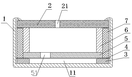
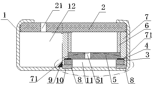
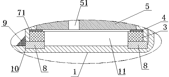
[0032] figure 2 It is a cross-sectional view of a columnar metal support column structure in an embodiment of the present invention; image 3 yes figure 2 Partial enlarged view of Figure 4 It is a schematic cross-sectional structure diagram of Embodiment 1 of the present invention; Figure 5 It is a top view of a columnar metal support column according to an embodiment of the present invention; Image 6 It is a top view of an insulating cavity according to an embodiment of the present invention; Figure 7 It is a cross-sectional view of an "L"-shaped support platform structure in Embodiment 1 of the present invention; Figure 8 yes Figure 7 Partial enlarged view of Figure 9 It is a top view of an "L"-shaped support platform according to an embodiment of the present invention. Such as Figure 2-9 As shown, a microphone includes an external packaging structure composed of a housing 1 and a circuit board 2, and the inside of the packaging structure is provided with a...

Embodiment 2

[0043] Figure 10 It is a cross-sectional view of the structure form of the second columnar metal support column in the embodiment of the present invention; Figure 11 It is a cross-sectional view of the structure of the "L"-shaped support platform in Embodiment 2 of the present invention. Such as Figure 10 , Figure 11As shown, the difference between the present embodiment and the first embodiment is that the sound hole 21 is arranged on the circuit board 2 in the surrounding area of ​​the metal ring 6, so that the first cavity 11 and the second cavity 12 are communicated. Forms the back cavity of the microphone. The microphone with this structure makes the volume of the rear cavity larger, which makes it easier to improve the ultimate sensitivity of the product and achieve the electrical performance required by the product.


PUM


Abstract

The invention discloses a microphone, which comprises an external package structure consisting of a shell and a circuit board. A parallel plate capacitor which consists of a membrane, a gasket and a polar plate is arranged in the package structure and installed on the bottom of the shell; a first cavity is formed between the membrane and the bottom of the shell; a metal ring and an insulating cavity sleeved on the periphery of the metal ring are arranged between the parallel plate capacitor and the circuit board; the two ends of the parallel plate capacitor are respectively electrically connected to the circuit board through the metal ring and the shell; acoustic holes are formed in the circuit board; a second cavity is formed between the insulating cavity and the side wall of the shell; and the first cavity and the second cavity are communicated. By arranging the acoustic holes at different positions on the circuit board, the volume of a rear cavity of the microphone can be increased, the limiting sensitivity of a product is improved, and electric performance required by the product is realized.

Description

technical field [0001] The present invention relates to the technical field of acoustic-electric transducers, and more specifically, to a microphone. Background technique [0002] With the progress of society and the development of technology, in recent years, as the volume of electronic products such as mobile phones and notebook computers has been continuously reduced, people have higher and higher requirements for the performance of these portable electronic products, which also require matching electronic products. Parts continue to shrink in size, performance and consistency. In this context, as one of the important parts of the above-mentioned portable electronic products, many new products have been introduced in the field of microphone products, among which the omni-directional back pole microphone is the representative product. [0003] For the working principle of ordinary omnidirectional back pole microphone products, as attached figure 1 It is a cross-sectional...

Claims


Application Information

Patent Timeline
Patent Type & Authority Patents(China)
IPC IPC(8): H04R1/04H04R1/08
Inventor 党茂强李欣亮王友王显彬
Owner GOERTEK MICROELECTRONICS CO LTD
Why Eureka
Try Eureka