A timing configuration method and system for a relay network
A configuration method and relay network technology, which is applied to multi-frequency code systems, synchronization devices, electrical components, etc., can solve the problem that relay stations cannot perform timing configuration, etc.
- Summary
- Abstract
- Description
- Claims
- Application Information
AI Technical Summary
Problems solved by technology
Method used
Image

Examples
Embodiment 1
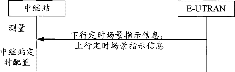
[0110] Such as image 3 As shown, E-UTRAN sends high-level signaling to the relay station, including downlink timing scenario indication information and uplink timing scenario indication information, where the downlink timing scenario indication information indicates that the downlink timing scenario in which the relay station is working is downlink scenario 1, and the uplink timing scenario indication The information indicates that the uplink timing scenario where the relay station works is uplink scenario 2b. The relay station has measured that the normal CP configuration is adopted at this time, the system is in FDD mode, and the relay station’s downlink backhaul link reception timing is (DL means downlink, B-R means backhaul link reception), the relay station uplink backhaul link transmission timing is (UL means uplink, B-T means backhaul link transmission), the corresponding downlink fixed delay Δ DL And uplink fixed delay Δ UL All are pre-arranged by the system. The re...
Embodiment 2
[0112] Such as Figure 4 As shown, E-UTRAN sends high-level signaling to the relay station, including downlink timing scenario indication information, indicating that the downlink timing scenario in which the relay station works is downlink scenario 3. The relay station has measured that the normal CP configuration is adopted at this time, the system is in FDD mode, and the downlink backhaul link reception timing of the relay station is The transmission timing of the uplink backhaul link of the relay station is Propagation delay is 1024T s , And according to the preset judgment threshold, the propagation delay is 624T s ~1568T s . The relay station performs timing configuration according to the locally measured timing information and the high-level signaling sent by the E-UTRAN. The configuration result is: the transmission start point of the downlink backhaul link is symbol k, the transmission end point is symbol 12, and the transmission length is 13-k symbols , The transmiss...
Embodiment 3
[0114] Such as Figure 5 As shown, E-UTRAN sends high-level signaling to the relay station, including downlink backhaul link transmission end information, indicating that the downlink backhaul link transmission end point of the relay station is symbol 13. The relay station has measured that the normal CP configuration is adopted at this time, the system is in FDD mode, and the relay station’s downlink backhaul link reception timing is The transmission timing of the uplink backhaul link of the relay station is Corresponding downlink fixed delay Δ DL And uplink fixed delay Δ UL They are all agreed upon by the system. The relay station performs timing configuration according to the locally measured timing information and the high-level signaling sent by the E-UTRAN. The configuration result is: the downlink timing scenario is downlink scenario 1, the transmission start point of the downlink backhaul link is symbol k+1, and the transmission end point is symbol 13. The transmissi...
PUM
 Abstract
Description
Claims
Application Information
 - R&D
- Intellectual Property
- Life Sciences
- Materials
- Tech Scout
- Unparalleled Data Quality
- Higher Quality Content
- 60% Fewer Hallucinations
Browse by: Latest US Patents, China's latest patents, Technical Efficacy Thesaurus, Application Domain, Technology Topic, Popular Technical Reports.
© 2025 PatSnap. All rights reserved.Legal|Privacy policy|Modern Slavery Act Transparency Statement|Sitemap|About US| Contact US: help@patsnap.com