expandable shaft

A shaft-aligned, gripping device technology, applied in the field of expanding the expandable shaft, can solve the problems of replacement core impact, easy to be affected by impact, damage to the profile, etc., to achieve weight reduction, easy disassembly, and cost increase Effect

Inactive Publication Date: 2011-12-21
WTK HLDG IVS
View PDF7 Cites 14 Cited by
  • Summary
  • Abstract
  • Description
  • Claims
  • Application Information

AI Technical Summary

Problems solved by technology

Extruded aluminum profile shafts do not always have sufficient mechanical strength, are susceptible to impacts and are relatively expensive to manufacture
If the shaft requires good centering and high strength at the same time, the shaft is usually made of ground steel and is very expensive to manufacture
Steel shafts also have significant weight and require additional and relatively expensive operating tooling during the installation and removal process
[0009] Also, due to the external shape, these types of shafts are susceptible to shock when changing the core
Damage to the profile can lead to sharp corners, thus perforating air cavities and vulnerable end pieces

Method used


Image

  • expandable shaft
  • expandable shaft
  • expandable shaft

Examples


Embodiment Construction

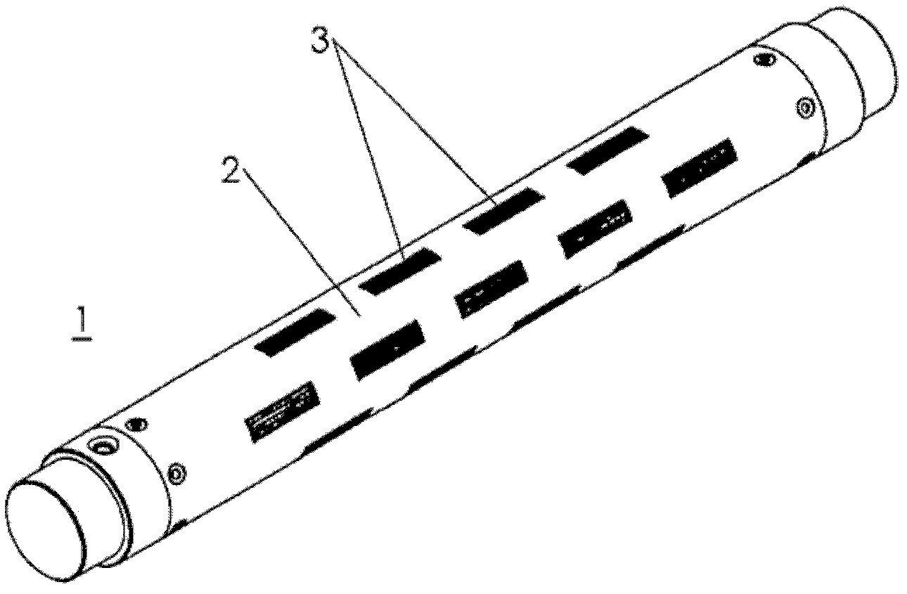
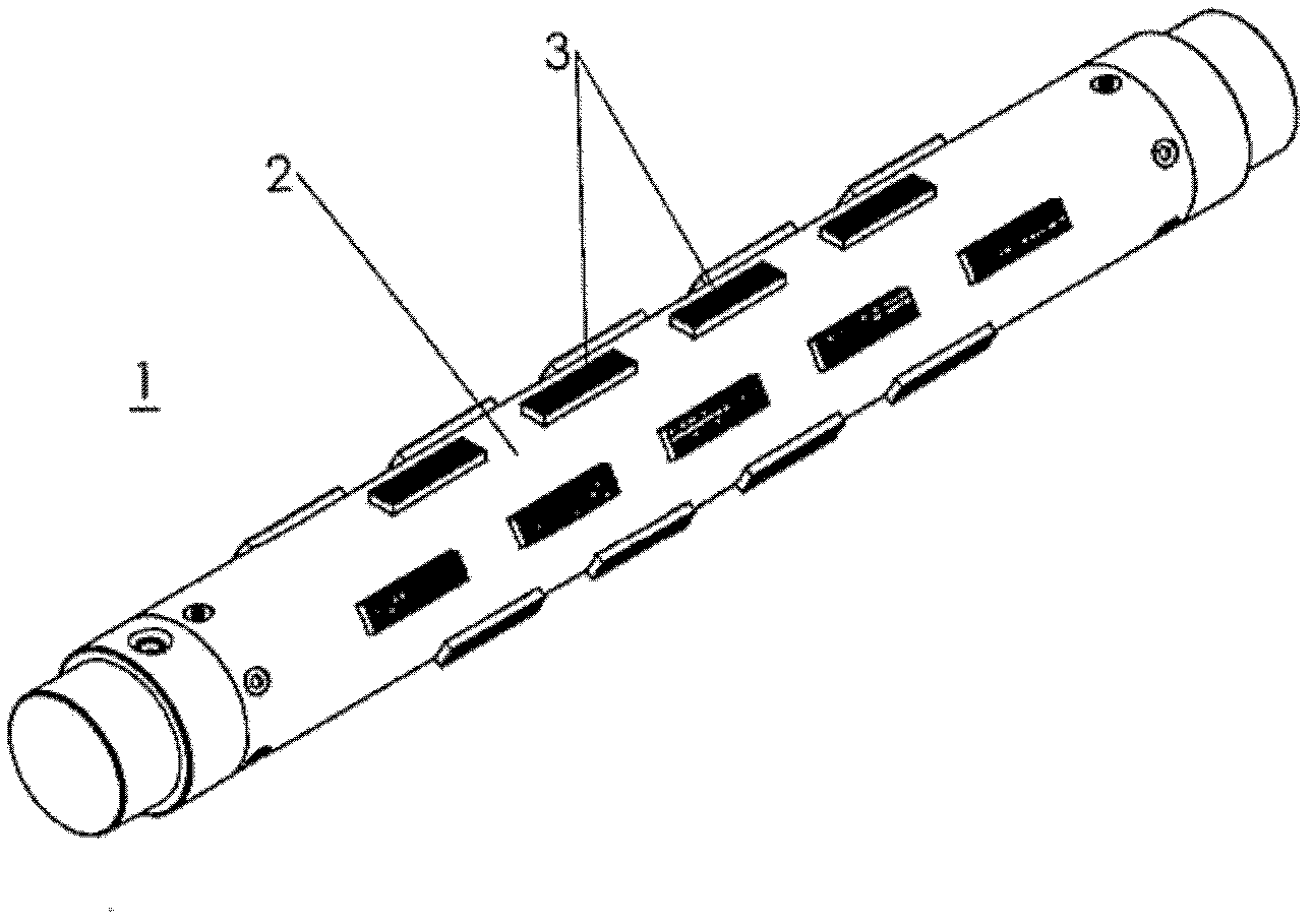
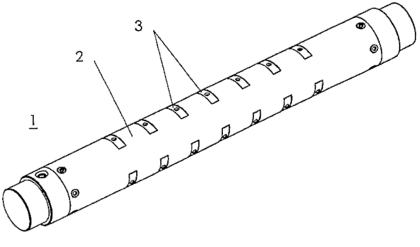
[0048] The present invention will be explained in more detail with reference to preferred embodiments shown in the drawings. In those figures, the reference number 1 refers to the expandable shaft according to the present invention. The expandable shaft 1 has an outer cylindrical tube 2 including a plurality of openings in which the holding device 3 is aligned. The holding device 3 can protrude along the radial direction of the shaft and beyond the tube. The holding device 3 is adapted to move radially between a first position and a second position according to an undisclosed inflatable cavity. in figure 1 , The holding device 3 is elongated along the longitudinal direction of the shaft 1, and the holding device 3 is in the first position. During the expansion of the undisclosed inflatable cavity, the holding device 3 will move from the first position to the second position, beyond figure 2 The external cylindrical tube 2 is disclosed. In the second position, the holding de...


PUM


Abstract

The present invention relates to an expandable shaft (1) for insertion into a core, the expandable shaft have a longitudinal extension and comprising: a profile (4), which extends in the longitudinal direction of the shaft, the profile comprising a plurality of longitudinal grooves (9); inflatable and expandable chambers (7) which are adapted to be arranged in the grooves (9); gripping means (3) which are arranged in connection to the expandable chambers (7), the gripping means (3) being adapted to radial movement between a first position and a second position in view of an expansion of the inflatable and expandable chambers so that the gripping means (3) are movable in a radial direction between a first position and a second position depending on an expansion of the expandable chambers (7) wherein an outer cylindrical tube (2) is arranged outside the profile (4), the outer cylindrical tube comprising a plurality of openings, and wherein the gripping means (3) are aligned with the openings of the tube so that the gripping means can project through and beyond the tube in a radial direction of the shaft during the expansion of the expandable chambers.

Description

Technical field [0001] The present invention relates to an expandable shaft for rotatably supporting a tubular core of a roller made of material, which must be supported during the winding or unwinding process. The material can be paper, or other types of reel materials, such as fabric, metal, plastic film, foil, tape, etc. The expandable shaft for inserting the core adopts a type having a longitudinal extension, and adopts a profile extending along the longitudinal direction of the shaft, the profile includes a plurality of longitudinal grooves, inflatable and expandable cavities, suitable for arrangement In the groove, and a holding device arranged to connect the inflatable and inflatable cavity, the holding device is adapted to be in the first position and the second position when the inflatable and inflatable cavity is inflated Move radially between. [0002] Furthermore, the invention relates to a method of expanding an expandable shaft. [0003] The holding device adopts th...

Claims


Application Information

Patent Timeline
Patent Type & Authority Applications(China)
IPC IPC(8): B65H75/24
CPCB65H75/243B65H75/2437
Inventor K.韦伯
Owner WTK HLDG IVS
Why Eureka
Try Eureka