Grid array antenna and its integrated structure

A technology of grid array and array antenna, which is applied in the direction of antenna, antenna array, electric long antenna, etc., and can solve the problems of poor antenna performance and so on

Inactive Publication Date: 2011-12-21
NANYANG TECH UNIV
View PDF3 Cites 36 Cited by
  • Summary
  • Abstract
  • Description
  • Claims
  • Application Information

AI Technical Summary

Problems solved by technology

As a result, existing grid array antennas perform poorly at mmWave frequencies

Method used


Image

  • Grid array antenna and its integrated structure
  • Grid array antenna and its integrated structure
  • Grid array antenna and its integrated structure

Examples


Embodiment Construction

[0066] The present invention will be further described below in conjunction with the accompanying drawings and reference numerals thereof.

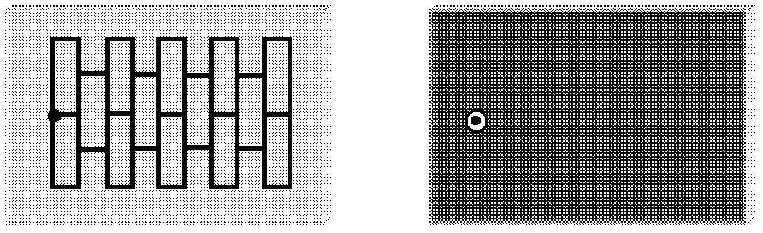
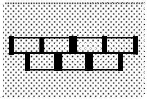
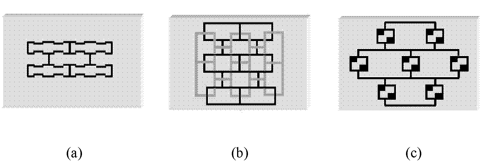
[0067] As shown in FIG. 8 , the phase of the radiating element is adjusted by changing the electrical lengths of the long and short sides of the grid other than the dotted line. The phase of the feed and radiating elements can also be compensated by means of phase adjusters or amplifiers. For example, an insertion amplifier can compensate for phase and amplitude. Inductors, capacitors or resonators can be considered as passive phase adjusters. Instead of using discrete chip inductors, capacitors or resonators, other integrated components may also be preferred. Figure 9 It is an integrated sensor used in the single-layer grid array antenna 900 . The antenna 900 includes a grid 902 formed by short sides 904 and long sides 912 . One or more short sides 904 are radiating elements. One or more radiating elements 904 contain integrated ind...


PUM


Abstract

A grid array antenna configured to operate with millimetre wavelength signals, the grid array antenna comprising a plurality of mesh elements and at least one radiation element; each mesh element comprising at least one long side and at least one short side operatively connected to the at least one long side; at least one of: the at least one radiating element, the at least one short side, and the at least one long side having compensation for improved antenna output for improved antenna radiation.

Description

technical field [0001] The invention relates to a grid array antenna and its integrated structure, in particular to a grid array antenna suitable for millimeter wavelength signals and its integrated structure. Background technique [0002] The concept of the grid array antenna was first proposed by Kraus in 1964, and there have been many studies on the grid array antenna but they all focused on relatively low microwave frequencies. Figure 1 is the basic arrangement of the grid of the grid array antenna, which is composed of a rectangular grid of microstrip lines arranged on a dielectric substrate. The other side of the dielectric substrate is supported by a metal ground layer, and the metal through-hole passes through the ground. The holes and slots on the layer are fed. Depending on the electrical length of each side of the grid, grid array antennas can be resonant or non-resonant. [0003] For the resonant grid array antenna, the grid side length on the dielectric substr...

Claims


Application Information

Patent Timeline
Patent Type & Authority Applications(China)
IPC IPC(8): H01Q21/00H01Q11/00
CPCH01Q21/24H01Q11/04H01Q11/02H01Q21/06
Inventor 张跃平孙梅
Owner NANYANG TECH UNIV
Why Eureka
Try Eureka