Method and device for uplink power control

A technology of power control and transmit power, applied in the field of communication, can solve the problem that there is no effective scheme for uplink power control in different frequency bands, etc.

Active Publication Date: 2011-12-28
DATANG MOBILE COMM EQUIP CO LTD
View PDF4 Cites 67 Cited by
  • Summary
  • Abstract
  • Description
  • Claims
  • Application Information

AI Technical Summary

Problems solved by technology

How to perform uplink power control on different frequency bands is currently no effective solution

Method used


Image

  • Method and device for uplink power control
  • Method and device for uplink power control
  • Method and device for uplink power control

Examples


Embodiment Construction

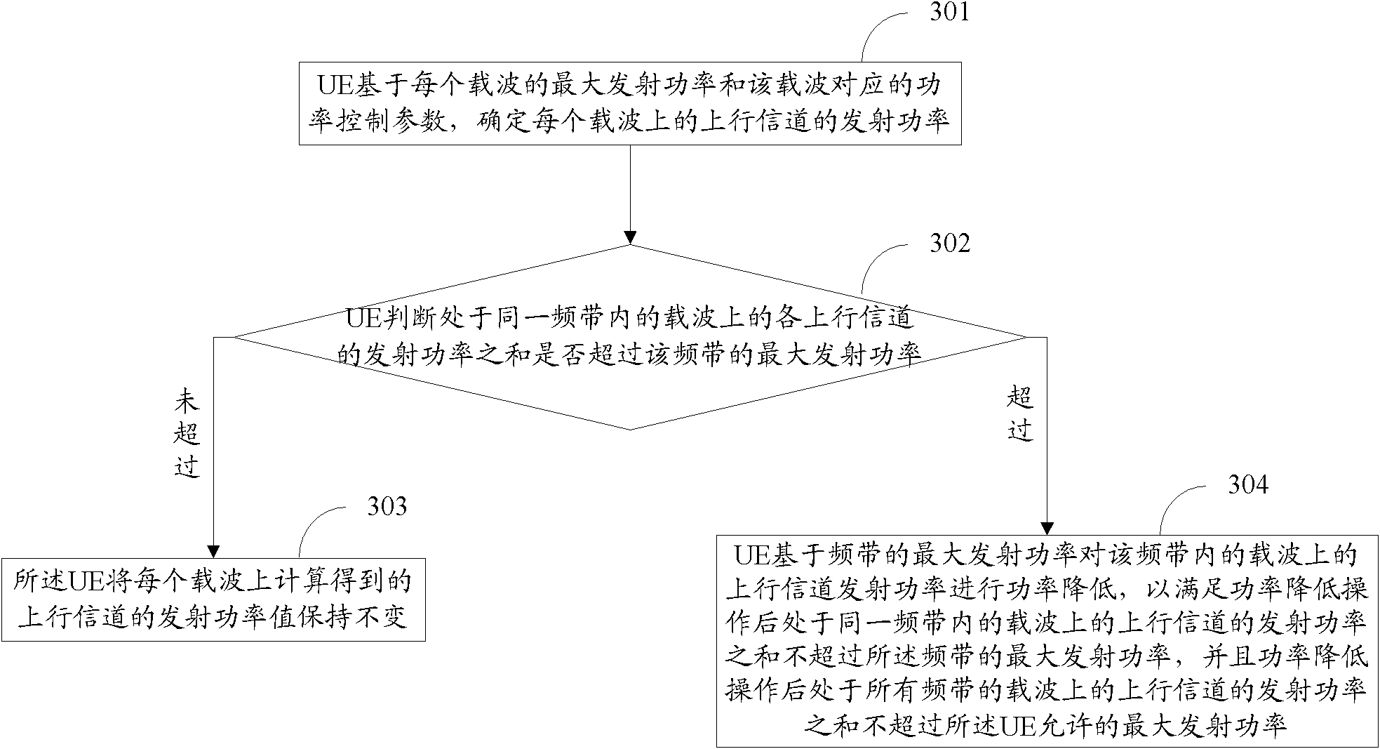
[0061] In the embodiment of the present invention, the maximum transmission power allowed by each band (frequency band) is pre-configured for the UE, and the UE judges whether it is necessary to adjust the transmission power of each uplink channel on the carrier in the same frequency band according to the maximum transmission power of the frequency band. If necessary , then perform corresponding operations to meet the requirement that the sum of the transmit powers of the uplink channels on the carriers in the same frequency band after the power reduction operation does not exceed the maximum transmit power of the frequency band, and the transmission power of the carriers in all frequency bands after the power reduction operation The sum of transmit powers of uplink channels does not exceed the maximum transmit power allowed by the UE. Band-specific power control is implemented. Wherein, the maximum transmission power of each frequency band configured in the UE is configured to ...


PUM


Abstract

Disclosed is an uplink power control method, for controlling that the sum of transmit power of all uplink channels in a sub-frame does not exceed maximum transmit power allowed by UE. The method comprises: the UE determining the transmit power of uplink channels on each carrier; for each frequency band, the UE judging whether the sum of the transmit power of the uplink channels on the carriers in the same frequency band exceeds the maximum transmit power of the frequency band; if not, the UE maintaining the calculated transmit power of the uplink channels on each carrier; and if yes, the UE reducing the transmit power of the uplink channels on the carriers in the frequency band based on the maximum transmit power of the frequency band, so as to ensure that the sum of the transmit power of the uplink channels on the carriers in the frequency band does not exceed the maximum transmit power of the frequency band and that the sum of the transmit power of the uplink channels in all the frequency bands does not exceed the maximum transmit power allowed by the UE. Also disclosed is a device for implementing the method.

Description

technical field [0001] The present invention relates to the communication field, in particular to a method and device for uplink power control. Background technique [0002] The LTE-A (Long Term Evolution-Advanced, upgraded long-term evolution) system introduces the CA (Carrier Aggregation, carrier aggregation) technology, such as figure 1 As shown, this technology is to aggregate some spectrum allocated to the existing system to form a large bandwidth. At this time, the uplink and downlink carriers in the system can be configured asymmetrically, that is, users may occupy N≥1 carriers for downlink transmission. M≥1 carriers perform uplink transmission. [0003] Carrier aggregation technology enables the terminal to work simultaneously on multiple cells (cells). For an FDD (Frequency Division Duplex, frequency division duplex) system, a cell includes a DL CC (Downlink Component Carrier, downlink component carrier) and a UL CC (Uplink Component Carrier, uplink component carr...

Claims


Application Information

Patent Timeline
Patent Type & Authority Applications(China)
IPC IPC(8): H04W52/14
CPCH04W52/346Y02B60/50H04W52/367H04W52/14H04W52/146
Inventor 高雪娟林亚男沈祖康
Owner DATANG MOBILE COMM EQUIP CO LTD
Why Eureka
Try Eureka