
taxi brake inhibit system

A technology of brakes and braking force, applied in the direction of brakes etc.

Active Publication Date: 2011-12-28
HYDRO AIRE AEROSPACE CORP
View PDF5 Cites 10 Cited by
  • Summary
  • Abstract
  • Description
  • Claims
  • Application Information

AI Technical Summary

Problems solved by technology

Additional electronic brake failure conditions may also occur where the brake system control unit (BSCU) generally no longer monitors will cause one or more of these failure effects

Method used


Image

  • taxi brake inhibit system
  • taxi brake inhibit system
  • taxi brake inhibit system

Examples


Embodiment Construction

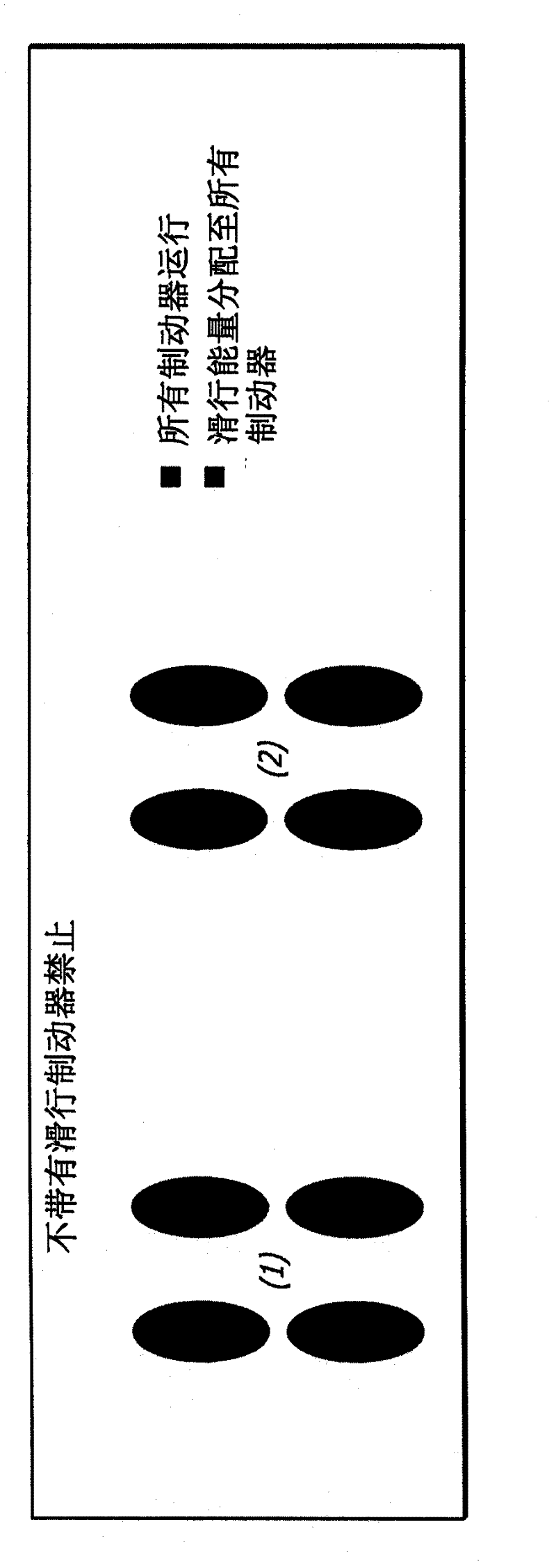
[0043] With reference to the drawings, which are provided by way of example and not by way of limitation, the present invention provides systems and methods for controlling a taxi brake inhibit mode of the brakes of an aircraft. refer to Figure 5 , the system 30 for controlling the taxi brake inhibit mode during operation of the aircraft brakes generally includes a brake system control unit (BSCU) 32 configured to control an electronic brake activation controller (EBAC) 34, the brake The system control unit is electrically connected with the electronic brake activation controller 34 through the system bus 36 . Further, the electronic brake activation controller is configured to control the operation of the landing gear, such as the operation of the landing gear 38, which includes the front wheel brake pair 40a, 40b connected to the electronic brake activation controller and the front wheel brake pair connected to the electronic brake activation controller. The pair of rear w...


PUM


Abstract

A taxi brake inhibit system overcomes problems of discontinuities in pedal 'feel' that can occur by use of a taxi brake inhibit system, by adding a new pedal 'feel' logic in which twice the brake force is commanded for a given brake pedal application when taxi brake inhibit is active. The taxi brake inhibit system relies upon two different brake force vs. brake pedal application curves to compensate for the difference in deceleration that is achieved for a given brake pedal application depending upon whether the taxi brake inhibit is active or inactive. Such system effectively eliminates undesirable deceleration bumps, yaw effects and changes in pedal feel during braking. The taxi brake inhibit feature is also shut off to both fore-aft brake pairs if any non-normal taxi brake inhibit condition exists on either fore-aft brake pair.

Description

[0001] Cross References to Related Applications [0002] This application is based on and claims Provisional Patent Application No. 61 / 148,248 filed January 29, 2009, Provisional Patent Application No. 61 / 225,519 filed July 14, 2009, and Formal Application No. 12 / 695121, the entire contents of which are incorporated herein by reference in their entirety. technical field [0003] The present invention relates generally to aircraft braking systems and more particularly to improvements in taxi brake inhibit systems that reduce carbon brake wear. Background technique [0004] Carbon brakes are installed in many modern aircraft designed to carry large passenger or cargo loads. This brake relies on the use of carbon composites as friction material and heat sink / sink. Stacks of carbon rotor disks and carbon stator disks are arranged coaxially along the wheel axis in an alternating sequence, with the rotor disks rotationally keyed to the wheel, while the stator disks are keyed to...

Claims


Application Information

Patent Timeline
Patent Type & Authority Applications(China)
IPC IPC(8): B60T8/00B60T8/17
CPCB60T8/1703B60T8/00Y02T50/80
Inventor G·H·迪夫里格J·勾万
Owner HYDRO AIRE AEROSPACE CORP
Learn More