Wind shielding gravel mechanism not vertical to ground

A non-vertical, sand and stone technology, applied in the field of wind and sand retaining wall structures, can solve the problems of waste of manpower and material resources and loss of original equipment, and achieve the effect of weakening handling and avoiding erosion

Inactive Publication Date: 2012-01-04
北京首创大气环境科技股份有限公司
View PDF4 Cites 11 Cited by
  • Summary
  • Abstract
  • Description
  • Claims
  • Application Information

AI Technical Summary

Problems solved by technology

Therefore, it is difficult for the existing upright anti-wind and sand retaining wall to achieve the ideal anti-wind and sand effect in areas with large amount of wind and sand and fast wind speed. At the same time, it will also cause waste of original equipment and loss of manpower and material resources in the secondary installation process.

Method used


Image

  • Wind shielding gravel mechanism not vertical to ground
  • Wind shielding gravel mechanism not vertical to ground
  • Wind shielding gravel mechanism not vertical to ground

Examples


Embodiment Construction

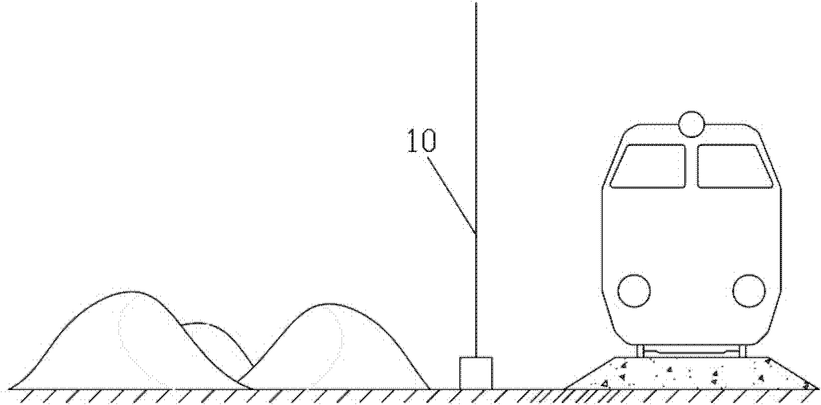
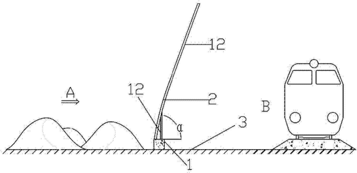
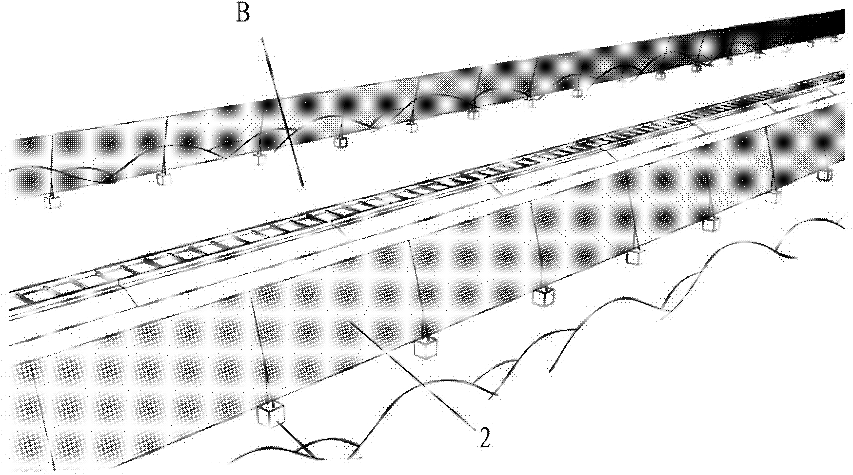
[0021] see Figure 2 ~ Figure 4 , which shows a preferred embodiment of a non-vertical ground windbreak sandstone mechanism of the present invention, including a base 1, a windbreak sandstone structure 2 installed on the base 1, and a windbreak sandstone structure 2 along the direction of wind movement (such as 2 and Figure 4 The direction A) shown in is inclined at an angle of 30 to 80 degrees with the installation surface 3 of the base 1 (such as figure 2 shown in the angle α), the angle α in this embodiment is the angle between the bottom tangent direction of the windshield sandstone structure 2 and the installation surface 3, of course, it is not difficult for those of ordinary skill in the art to understand , according to the characteristics of different geographical and geological environments, the windshield sandstone structure 2 of the present invention can be perpendicular to the installation surface 3 at the installation position, or even opposite to the movement ...


PUM


Abstract

The invention relates to a wind shielding gravel mechanism not vertical to the ground. The wind shielding gravel mechanism comprises a base, a wind shielding gravel structure installed on the base; in the movement direction of wind, the wind shielding gravel structure is in an arrangement with an inclined angle of 30-80 degrees with the installment plane of the base; in addition, the wind shielding gravel structure is provided with a plurality of through holes with aperture ratio of 20-80%, at least a part of windward side of the wind shielding gravel structure is a curve structure. The wind shielding gravel structure not vertical to ground can change wind direction on the ground on the basis of an aerodynamic principle and enables wind to be output in direction parallel to the installment direction of the wind shielding gravel mechanism, and thus corrosion phenomenon can be avoided effectively; in addition, due to the change of wind direction and shielding of the wind shielding gravel mechanism, wind power in the wind shielding gravel mechanism is reduced obviously, and thus the wind shielding gravel mechanism can be used for reducing the sand carrying capacity of wind can be effectively weakened, and the damage of sand flow to railways, highways and other traffic facilities can be further prevented.

Description

technical field [0001] The invention relates to a wind-sand retaining wall structure, in particular to a wind-sand-stone net wall on a non-vertical ground. Background technique [0002] Existing wind-sand retaining wall structure 10 overwhelming majority all is installed vertically to the ground, as figure 1 shown. [0003] This kind of structure is convenient for design and installation. However, for some areas with large amount of wind and sand and fast wind speed, such as the northwestern part of China, the maximum wind speed can reach more than 30 s / m. Therefore, the wind and sand retaining wall structure or windbreak wall structure installed vertically is very easy to form turbulent flow due to the wind close to the surface under the condition of wall barrier, and, over time, erosion will occur. [0004] After the erosion occurs, the sand-fixing body for windbreaks is prone to wind and sand flow directly blowing into the windshield area from the ground. Thereby more ...

Claims


Application Information

Patent Timeline
Patent Type & Authority Applications(China)
IPC IPC(8): E01F7/02
Inventor 郑向军屈建军薛峰张克存
Owner 北京首创大气环境科技股份有限公司
Why Eureka
Try Eureka