Optical touch system

A touch system, optical technology, applied in the direction of instrument, electrical digital data processing, data processing input/output process, etc., can solve the problem of reduced sensing accuracy, insufficient brightness, uniform image quality, and insufficient brightness. problem, to ensure the image quality, improve the overall brightness and light uniformity, and improve the accuracy

Inactive Publication Date: 2012-01-04
QISDA SUZHOU +1
View PDF5 Cites 0 Cited by
  • Summary
  • Abstract
  • Description
  • Claims
  • Application Information

AI Technical Summary

Problems solved by technology

[0005] However, when the size of the indicating plane 10 is large to a certain extent (for example, 23.6 inches), the structure of the known light source 14 will have insufficient brightness (the brightness will decrease at a place far away from the light-emitting unit 142) and the light uniformity will not be sufficient. Good (Because the brightness of the light output position near the light emitting unit 142 is high, and the brightness far away from the light emitting unit 142 will decrease, resulting in poor light uniformity of the light source 14 as a whole)
Insufficient brightness or poor light uniformity will affect the quality of the image sensed by the image sensing unit 12, reducing the sensing accuracy

Method used


Image

  • Optical touch system
  • Optical touch system
  • Optical touch system

Examples


Embodiment Construction

[0020] In order to have a further understanding of the purpose, structure, features, and functions of the present invention, the following detailed descriptions are provided in conjunction with the embodiments.

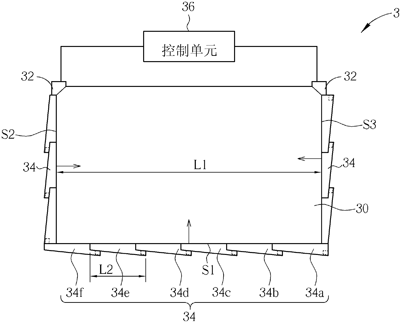
[0021] see figure 2 , figure 2 It is a schematic diagram of the optical touch system 3 according to the first embodiment of the present invention. Such as figure 2 As shown, the optical touch system 3 includes an indication plane 30 , two image sensing units 32 , N light sources 34 and a control unit 36 ​​. The control unit 36 ​​is electrically connected to the two image sensing units 32 and the N light sources 34 for controlling the image sensing units 32 to sense images and controlling the light sources 34 to emit light. Two image sensing units 32 are disposed at two corners of the indicating plane 30 , and N light sources 34 are disposed on the side S1 of the indicating plane 30 , wherein N is a positive integer greater than 1, and the N light sources 34 are ...


PUM


Abstract

The invention provides an optical touch system. The system comprises an indication plane, two image sensing units and N light sources, wherein N is a positive integer which is more than 1; the two image sensing units are arranged at the two corners of the indication plane; the N light sources are arranged on the sides of the indication plane and adjacent to one another; each light source comprises a light guide plate and a light-emitting unit; the light-emitting unit is arranged on the side of the light guide plate; the light guide plate of the ith light source in the N light sources is partially overlapped with the light-emitting unit of the (i+1)th light source; and i is a positive integer which is less than or equal to (N-1). The optical touch system can ensure the quality of images sensed by the image sensing units, so that object sensing accuracy can be effectively improved.

Description

technical field [0001] The present invention relates to an optical touch system, in particular to an optical touch system that can effectively improve overall brightness and light uniformity. Background technique [0002] With the maturity of the touch system, electronic devices with large size and multi-touch technology will become the mainstream in the future. At present, compared with other touch technologies, such as resistive, capacitive, ultrasonic or projection image, the optical touch system has the advantages of lower cost and easier implementation. [0003] see figure 1 , figure 1 It is a schematic diagram of an optical touch system 1 in the prior art. Such as figure 1 As shown, the optical touch system 1 includes an indicating plane 10 , two image sensing units 12 , three light sources 14 and a control unit 16 . The two image sensing units 12 are respectively disposed at two opposite corners of the indicating plane 10 . The three light sources 14 are respect...

Claims


Application Information

Patent Timeline
IPC IPC(8): G06F3/042
Inventor 唐建兴江长轩李俊仁陈志名
Owner QISDA SUZHOU
Why Eureka
Try Eureka