Optical imaging lens

a technology of optical imaging and lens, applied in the field of optical imaging lenses, can solve the problems of difficult balance between the requirements of good imaging quality and the current optical imaging lens, and achieve the effects of ensuring imaging quality, enhancing telephoto function, and reducing system length of optical imaging lens

Active Publication Date: 2022-02-03
GENIUS ELECTRONICS OPTICAL XIAMEN
View PDF5 Cites 0 Cited by
  • Summary
  • Abstract
  • Description
  • Claims
  • Application Information

AI Technical Summary

Benefits of technology

[0004]In the light of the above, various embodiments of the present invention propose an optical imaging lens of five lens elements which has reduced system length of the optical imaging lens, ensured imaging quality, an enhanced telephoto function, good optical performance and is technically possible. The optical imaging lens of five lens elements of the present invention from an object side to an image side in order along an optical axis has a first lens element, a second lens element, a third lens element, a fourth lens element and a fifth lens element. Each of the first lens element, the second lens element, the third lens element, the fourth lens element and the fifth lens element respectively has an object-side surface which faces toward the object side and allows imaging rays to pass through as well as an image-side surface which faces toward the image side and allows the imaging rays to pass through.

Problems solved by technology

However, a current optical imaging lens is difficult to balance the requirements of good imaging quality, a lighter, thinner, shorter and smaller volume and a telephoto function.

Method used


Image

  • Optical imaging lens
  • Optical imaging lens
  • Optical imaging lens

Examples


first embodiment

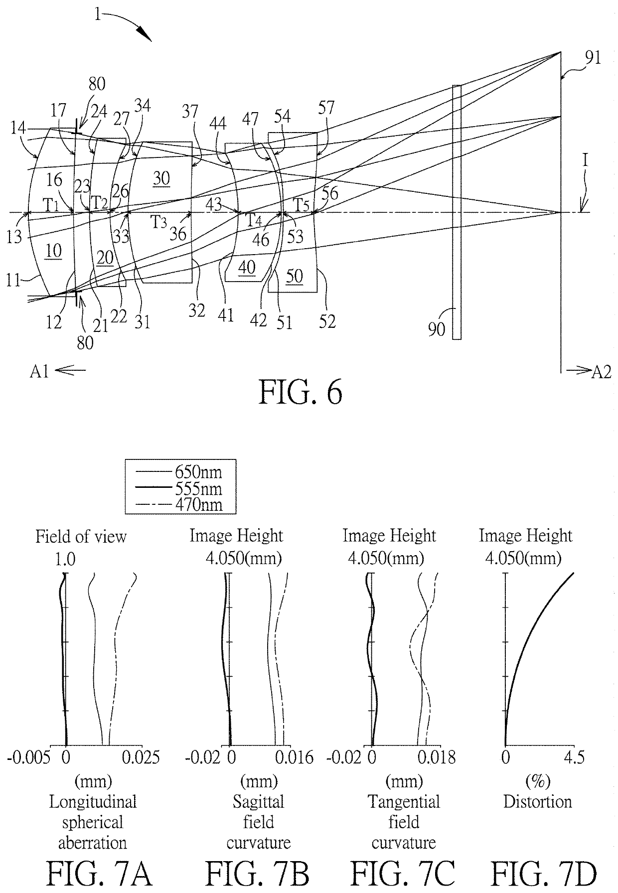
[0092]Please refer to FIG. 6 which illustrates the first embodiment of the optical imaging lens 1 of the present invention. Please refer to FIG. 7A for the longitudinal spherical aberration on the image plane 91 of the first embodiment; please refer to FIG. 7B for the field curvature aberration on the sagittal direction; please refer to FIG. 7C for the field curvature aberration on the tangential direction; and please refer to FIG. 7D for the distortion aberration. The Y axis of the spherical aberration in each embodiment is “field of view” for 1.0. The Y axis of the field curvature aberration and the distortion aberration in each embodiment stands for the “image height” (ImgH), which is 4.050 mm.

[0093]The optical imaging lens 1 of the first embodiment is mainly composed of five lens elements with refracting power, an aperture stop 80, and an image plane 91. The aperture stop 80 is provided between the first lens element 10 and the second lens element 20.

[0094]The first lens element...

second embodiment

[0106]Please refer to FIG. 8 which illustrates the second embodiment of the optical imaging lens 1 of the present invention. It is noted that from the second embodiment to the following embodiments, in order to simplify the figures, only the components different from what the first embodiment has, and the basic lens elements will be labeled in figures. Other components that are the same as what the first embodiment has, such as a convex surface or a concave surface, are omitted in the following embodiments. Please refer to FIG. 9A for the longitudinal spherical aberration on the image plane 91 of the second embodiment, please refer to FIG. 9B for the field curvature aberration on the sagittal direction, please refer to FIG. 9C for the field curvature aberration on the tangential direction, and please refer to FIG. 9D for the distortion aberration. The components in this embodiment are similar to those in the first embodiment, but the optical data such as the refracting power, the ra...

third embodiment

[0108]Please refer to FIG. 10 which illustrates the third embodiment of the optical imaging lens 1 of the present invention. Please refer to FIG. 11A for the longitudinal spherical aberration on the image plane 91 of the third embodiment; please refer to FIG. 11B for the field curvature aberration on the sagittal direction; please refer to FIG. 11C for the field curvature aberration on the tangential direction; and please refer to FIG. 11D for the distortion aberration. The components in this embodiment are similar to those in the first embodiment, but the optical data such as the refracting power, the radius, the lens thickness, the aspheric surface or the back focal length in this embodiment are different from the optical data in the first embodiment. Besides, in this embodiment, a periphery region 57 of the image-side surface 52 of the fifth lens element 50 is convex.

[0109]The optical data of the third embodiment of the optical imaging lens are shown in FIG. 26 while the aspheric...


PUM


Abstract

An optical imaging lens includes a first lens element to a fifth lens element from an object side to an image side in order along an optical axis. The first lens element has positive refracting power and a periphery region of the image-side surface of the first lens element is concave, a periphery region of the object-side surface of the second lens element is convex, a periphery region of the object-side surface of the third lens element is convex, the fifth lens element has negative refracting power and optical axis region of the object-side surface of the fifth lens element is concave to satisfy (G12+G23+G34)/(G45+T5)≥2.500 and EFL*Fno/HFOV≥3.500 mm/degree.

Description

BACKGROUND OF THE INVENTION1. Field of the Invention[0001]The present invention generally relates to an optical imaging lens. Specifically speaking, the present invention is directed to an optical imaging lens for use in such as a mobile phone, a camera, a tablet personal computer, or a personal digital assistant (PDA) and for taking pictures or for recording videos.2. Description of the Prior Art[0002]In recent years, an optical imaging lens improves along with its wider and wider applications. In addition to the requirements of a lighter, thinner, shorter and smaller optical imaging lens with improved imaging quality such as better aberration or chromatic aberration, a telephoto function may be added. However, a current optical imaging lens is difficult to balance the requirements of good imaging quality, a lighter, thinner, shorter and smaller volume and a telephoto function.[0003]Taking the practical production problems such as lens material characteristics, fabrication, assembl...

Claims


Application Information

Patent Timeline
Patent Type & Authority Applications(United States)
IPC IPC(8): G02B13/00G02B9/60G02B13/02G02B27/00H04N5/225
CPCG02B13/0045G02B9/60H04N5/2254G02B27/0025G02B13/02G02B3/04H04N23/55
Inventor JHANG, JIA-SINLIN, MAOZONGWANG, ZHAO
Owner GENIUS ELECTRONICS OPTICAL XIAMEN
Why Eureka
Try Eureka