zoom lens

A zoom lens and lens group technology, applied in the field of zoom lenses, can solve the problem of inability to take into account the freedom of optical design and manufacturing costs, and achieve the effects of good optical characteristics, reduced production costs, and reduced use quantity

Active Publication Date: 2016-01-06
SINTAI OPTICAL SHENZHEN CO LTD +1
View PDF4 Cites 0 Cited by
  • Summary
  • Abstract
  • Description
  • Claims
  • Application Information

AI Technical Summary

Problems solved by technology

[0005] The technical problem to be solved by the present invention is to provide a zoom lens that can use fewer optical components to achieve the zoom function in view of the defect that the zoom lens in the prior art cannot take into account the degree of freedom of optical design and low manufacturing cost. Can provide good optical characteristics and low manufacturing cost

Method used


Image

  • zoom lens
  • zoom lens
  • zoom lens

Examples


no. 1 example

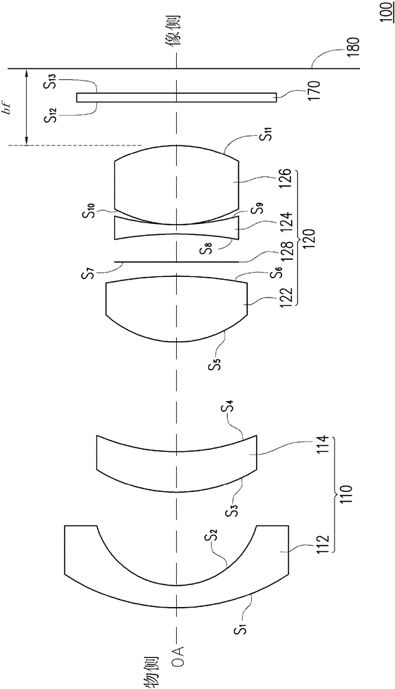
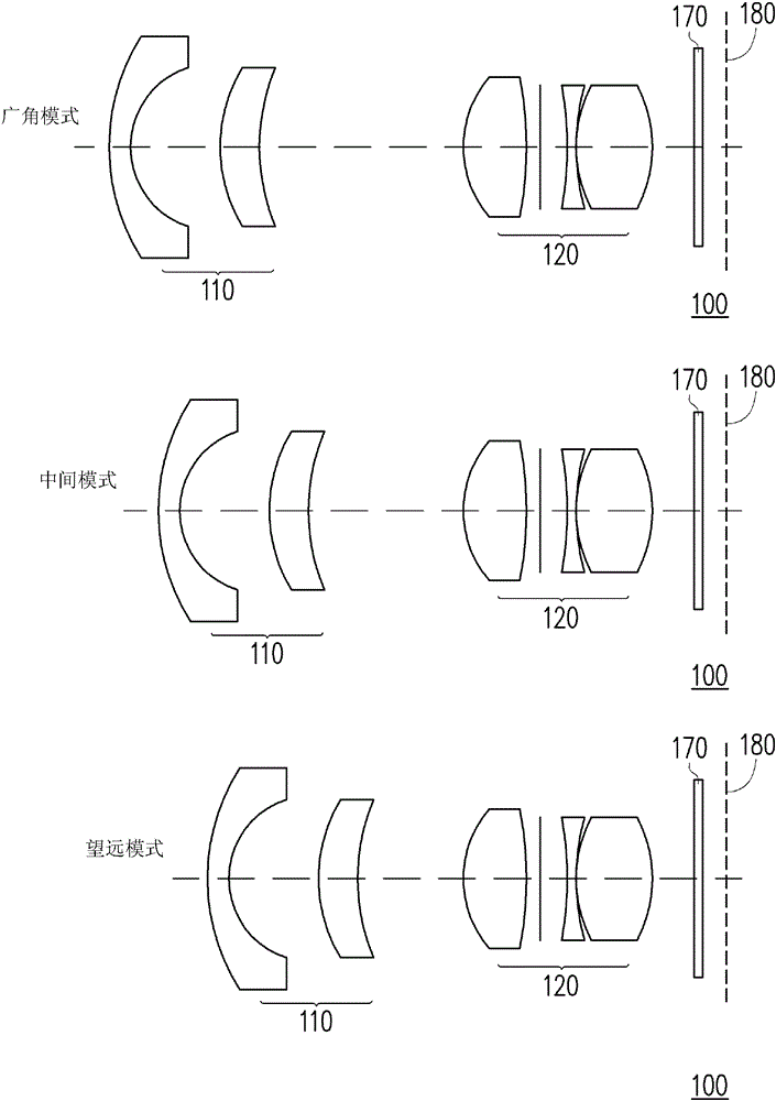
[0020] Figure 1A It is a schematic diagram of the zoom lens according to the first embodiment of the present invention. Please refer to Figure 1A , all optical components of the zoom lens 100 are arranged between the object side and the image side along the optical axis OA. The zoom lens 100 includes in sequence from the object side to the image side: a first lens group 110 and a second lens group 120 . The first lens group 110 has negative optical power (i.e. negative refractive power). The first lens group 110 includes in sequence from the object side to the image side: a negative meniscus lens 112 and a positive meniscus lens 114. The convex surface of the negative meniscus lens 112 faces the object side. The convex surface of the positive meniscus lens 114 faces the object side. The second lens group 120 has positive optical power (ie, positive refractive power). The second lens group 120 includes in sequence from the object side to the image side: a positive convex len...

no. 2 example

[0077] image 3 It is a schematic diagram of the zoom lens according to the second embodiment of the present invention. Please refer to image 3 , zoom lens 300 with Figure 1A The zoom lens 100 in has a similar structure.

[0078] Similarly, image 3 The zoom lens 300 includes in sequence from the object side to the image side: a first lens group 310 and a second lens group 320 . The first lens group 310 has negative optical power (i.e. negative refractive power). The first lens group 310 includes in sequence from the object side to the image side: a negative meniscus lens 312 and a positive meniscus lens 314. The convex surface of the negative meniscus lens 312 faces the object side. The convex surface of the positive meniscus lens 314 faces the object side. The second lens group 320 has positive optical power (ie, positive refractive power). The second lens group 320 includes in sequence from the object side to the image side: a positive convex lens 322 , a negative bicon...

no. 3 example

[0100] Figure 5 It is a schematic diagram of the zoom lens according to the third embodiment of the present invention. Please refer to Figure 5 , zoom lens 500 with Figure 1A The zoom lens 100 in has a similar structure.

[0101] Similarly, Figure 5 The zoom lens 500 includes in sequence from the object side to the image side: a first lens group 510 and a second lens group 520 . The first lens group 510 has negative optical power (i.e. negative refractive power). The first lens group 510 includes in sequence from the object side to the image side: a negative meniscus lens 512 and a positive meniscus lens 514. The convex surface of the negative meniscus lens 512 faces the object side. The convex surface of the positive meniscus lens 514 faces the object side. The second lens group 520 has positive optical power (ie, positive refractive power). The second lens group 520 includes in sequence from the object side to the image side: a positive convex lens 522 , a negative b...


PUM


Abstract

The invention relates to a zooming lens. The zooming lens sequentially comprises a first lens system and a second lens system from an object side to an image side. The first lens system has a negative optical capability, and sequentially comprises a negative concavo-convex lens and a positive concavo-convex lens from the object side to the image side, wherein both the concave surface of the negative concavo-convex lens and the concave surface of the positive concavo-convex lens face the object side. The second lens system has a positive optical capability, and sequentially comprises a positive convex lens, a negative biconcave lens and a positive biconcave lens. The first lens system and the second lens system are suitable for moving between the object side and the image side to ensure that the conversion of the zooming lens is conducted among a wide-angle mode, a middle mode and a telescoping mode.

Description

technical field [0001] The present invention relates to a lens, and in particular to a zooming lens. Background technique [0002] With the advancement of technology, many video or camera equipment have been developed, such as projectors, digital video cameras (Digital Video Camera, DVC), digital cameras and other imaging devices. [0003] A zoom lens is one of the important components of such imaging devices. By moving different lens groups in the zoom lens, the focal length of the zoom lens changes accordingly, which can increase the application flexibility of the zoom lens. Traditionally, most zoom lenses use multiple groups of actions to perform zooming operations. [0004] However, a zoom lens employing multiple groups of motion requires the use of multiple optical components. Because the zoom lens contains too many optical components, the optical length of the zoom lens cannot be shortened, and the price cannot be reduced. On the other hand, if the number of optica...

Claims


Application Information

Patent Timeline
Patent Type & Authority Patents(China)
IPC IPC(8): G02B15/177G02B1/04G02B1/00
Inventor 李赞桦
Owner SINTAI OPTICAL SHENZHEN CO LTD
Why Eureka
Try Eureka