Optical lenses and imaging equipment

An optical lens and lens technology, applied in optics, optical components, instruments, etc., can solve the problems of lens temperature performance degradation, resolution effect, and high cost of glass aspherical lenses

Active Publication Date: 2020-10-23
NINGBO SUNNY AUTOMOTIVE OPTECH
View PDF8 Cites 0 Cited by
  • Summary
  • Abstract
  • Description
  • Claims
  • Application Information

AI Technical Summary

Problems solved by technology

[0007] Under normal circumstances, in order to meet the needs of miniaturization of optical lenses, the solution of compressing the total optical length of the lens is usually adopted, but the resolution will be significantly affected
At the same time, the imaging quality can also be improved by increasing the use of aspheric lenses, but the cost of glass aspheric lenses is relatively high, and excessive use of plastic aspheric lenses will lead to a decrease in the temperature performance of the lens
[0008] In particular, for cameras that work in outdoor environments such as surveillance cameras or vehicle cameras, on the one hand, the working environment is changeable, and it is necessary to maintain perfect resolution no matter whether it is hot or cold, rainy or snowy. On the other hand, its installation space is limited

Method used


Image

  • Optical lenses and imaging equipment
  • Optical lenses and imaging equipment
  • Optical lenses and imaging equipment

Examples


no. 1 example

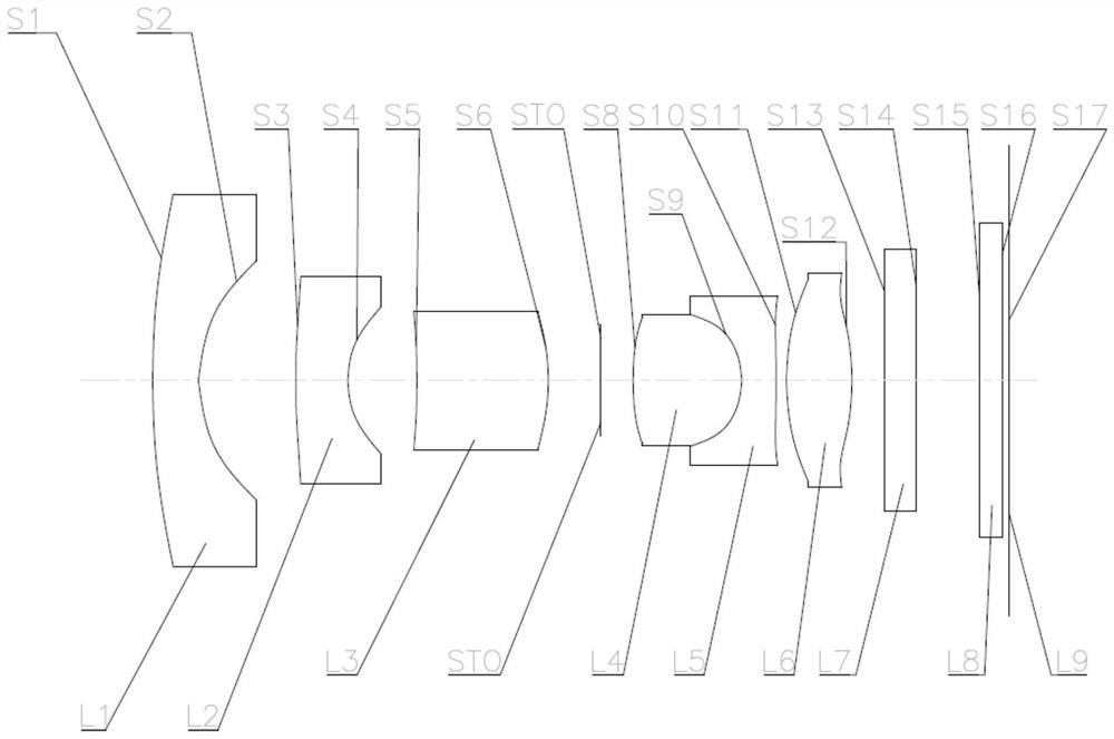
[0093] Such as figure 1As shown, the optical lens according to the first embodiment of the present invention includes in sequence from the object side to the image side: a meniscus-shaped first lens L1 with negative refractive power, a first surface S1 convex to the object side and a concave first surface S1 The second surface S2 on the image side, and the first lens L1 is a glass aspheric lens; the meniscus-shaped second lens L2 with negative power has a first surface S3 convex to the object side and concave to the image side The second surface S4 of the second surface S4; the meniscus-shaped third lens L3 with positive refractive power, with the first surface S5 concave to the object side and the second surface S6 convex to the image side; the stop STO; the fourth lens glued to each other Lens L4 and the fifth lens L5, wherein the fourth lens L4 is a biconvex shape with positive refractive power, has a first surface S8 convex to the object side and a second surface S9 convex...

no. 2 example

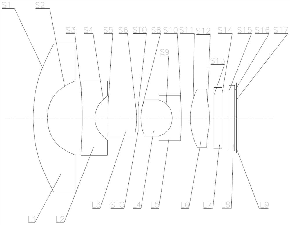
[0107] Such as figure 2 As shown, the optical lens according to the second embodiment of the present invention includes in sequence from the object side to the image side: a meniscus-shaped first lens L1 with negative power, a first surface S1 convex to the object side and a concave first surface S1 The second surface S2 on the image side, and the first lens L1 is a glass aspheric lens; the second lens L2 of a biconcave shape with negative power has a first surface S3 that is concave toward the object side and is concave toward the image side The second surface S4 of the second surface S4; the third lens L3 of biconvex shape with positive refractive power, has the first surface S5 convex to the object side and the second surface S6 convex to the image side; the diaphragm STO; the fourth lens L3 glued to each other Lens L4 and the fifth lens L5, wherein the fourth lens L4 is a biconvex shape with positive refractive power, has a first surface S8 convex to the object side and a...


PUM


Abstract

The invention provides an optical lens and an imaging apparatus. The optical lens sequentially comprises, from an object side to an image side, a first lens which is a crescent lens with negative focal power and is a glass aspherical lens, and of which the object side surface is a convex surface and the image side surface is a concave surface; a second lens which is provided with negative focal power, and of which the image side surface is a concave surface; a third lens which is provided with positive focal power, and of which the image side surface is convex; a fourth lens; a fifth lens glued with the fourth lens; and a sixth lens which is provided with positive focal power. According to the optical lens and the imaging apparatus, high resolution can be obtained while the miniaturizationof the optical lens is retained.

Description

technical field [0001] The invention relates to the field of optical lens and imaging equipment, in particular to the optical lens and imaging equipment capable of obtaining high resolution while keeping the lens miniaturized. Background technique [0002] Imaging devices such as camera-mounted mobile devices and digital still cameras using, for example, charge-coupled devices (CCD) and complementary metal-oxide semiconductors (CMOS) as solid-state imaging elements are well known. [0003] With the development of science and technology, the resolution requirements of optical lenses are getting higher and higher, from the original megapixels to the direction of tens of millions of pixels, and high-pixel lenses are becoming more and more popular. [0004] In addition, with the popularization of mobile devices, more and more small-sized imaging devices need to be applied, for example, imaging devices applied to mobile phones have very high requirements for small sizes. [0005...

Claims


Application Information

Patent Timeline
Patent Type & Authority Patents(China)
IPC IPC(8): G02B13/00
CPCG02B13/0045
Inventor 王东方姚波谢前森
Owner NINGBO SUNNY AUTOMOTIVE OPTECH
Why Eureka
Try Eureka