Object sensing system and control method thereof

A technology for sensing systems and objects, applied in instruments, electrical digital data processing, input/output processes of data processing, etc. Ensuring the effect of image quality and accuracy improvement

Inactive Publication Date: 2012-11-21
QISDA SUZHOU +1
View PDF0 Cites 0 Cited by
  • Summary
  • Abstract
  • Description
  • Claims
  • Application Information

AI Technical Summary

Problems solved by technology

If each light-emitting unit 14a, 14b, 14c emits light at the same time and for the same time, the brightness of some specific positions around the indicator plane 10 will be too bright or too dark, which will also affect the sensed brightness. Image quality reduces sensing accuracy

Method used


Image

  • Object sensing system and control method thereof
  • Object sensing system and control method thereof
  • Object sensing system and control method thereof

Examples


Embodiment Construction

[0038] In order to have a further understanding of the purpose, structure, features, and functions of the present invention, the following detailed descriptions are provided in conjunction with the embodiments.

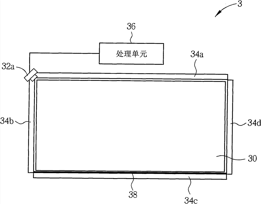
[0039] see figure 2 , figure 2 is a schematic diagram of an object sensing system 3 according to an embodiment of the present invention. Such as figure 2 As shown, the object sensing system 3 includes an indicating plane 30 , a first image sensing unit 32 a , four light emitting units 34 a , 34 b , 34 c , 34 d , a processing unit 36 ​​and a reflection unit 38 . The indicating plane 30 is used for indicating the position of the object. The first image sensing unit 32 a is disposed at a first corner of the indicating plane 30 . The light emitting units 34 a , 34 b , 34 c , 34 d are arranged around the indicating plane 30 . The reflective unit 38 is also disposed around the indicating plane 30 and located on the same side as the light emitting unit 34c. figure ...


PUM


Abstract

The invention discloses an object sensing system and a control method thereof. The object sensing system comprises an indication plane, a first image sensing unit and a plurality of light-emitting units and processing units. The indication plane is used for the object to indicate a position. The first image sensing unit is arranged at a first corner of the indication plane. The plurality of light-emitting units are arranged around the indication plane. Each light-emitting unit corresponds to at least one of the plurality of working hours, each working hour is respectively provided with at least one exposure time, and each exposure time respectively corresponds to at least one of the light-emitting units. The processing units are electrically connected with the first image sensing unit andthe light-emitting units. The processing units control the light-emitting units to emit light according to each exposure time and control the first image sensing unit to sense the first image concerning the indication plane within each working hour. The system and the method of the invention can effectively improve sensing accuracy.

Description

technical field [0001] The present invention relates to an object sensing system and its control method, in particular to an object sensing system and its control method which can effectively improve the sensing accuracy. Background technique [0002] With the maturity of the touch system, electronic devices with large size and multi-touch technology will become the mainstream in the future. At present, compared with other methods, such as resistive, capacitive, ultrasonic or projected image, the optical touch system has the advantages of lower cost and easier implementation. [0003] see figure 1 , figure 1 It is a schematic diagram of an optical touch system 1 in the prior art. Such as figure 1 As shown, the optical touch system 1 includes an indication plane 10 , two image sensing units 12 a , 12 b , three light emitting units 14 a , 14 b , 14 c and a processing unit 16 . The image sensing units 12a, 12b are disposed at two opposite corners of the indicating plane 10...

Claims


Application Information

Patent Timeline
Patent Type & Authority Patents(China)
IPC IPC(8): G06F3/042
Inventor 李俊仁张正宽赖育稚毛昭凯沈纬哲蔡华骏
Owner QISDA SUZHOU
Why Eureka
Try Eureka