Imaging apparatus

a technology of imaging apparatus and slit, which is applied in the field of imaging apparatus to achieve the effect of sufficient image quality for observation

Pending Publication Date: 2021-02-25
CANON KK
View PDF4 Cites 0 Cited by
  • Summary
  • Abstract
  • Description
  • Claims
  • Application Information

AI Technical Summary

Benefits of technology

[0003]One of problems to be solved by an embodiment disclosed in this specification is to ensure image quality sufficiently for observation. However, the problem is not limited to this, and obtaining functions and effects derived by configurations shown in an embodiment configured to implement the present invention to be described later can also be defined as another problem to be solved by the embodiment disclosed in this specification and the like.

Problems solved by technology

One of problems to be solved by an embodiment disclosed in this specification is to ensure image quality sufficiently for observation.

Method used


Image

  • Imaging apparatus
  • Imaging apparatus
  • Imaging apparatus

Examples


Embodiment Construction

[0011]An imaging apparatus according to an embodiment will now be described with reference to the accompanying drawings. Note that the embodiment is not limited to the following contents. In addition, the contents described in one embodiment or modification are similarly applied to another embodiment or modification in principle.

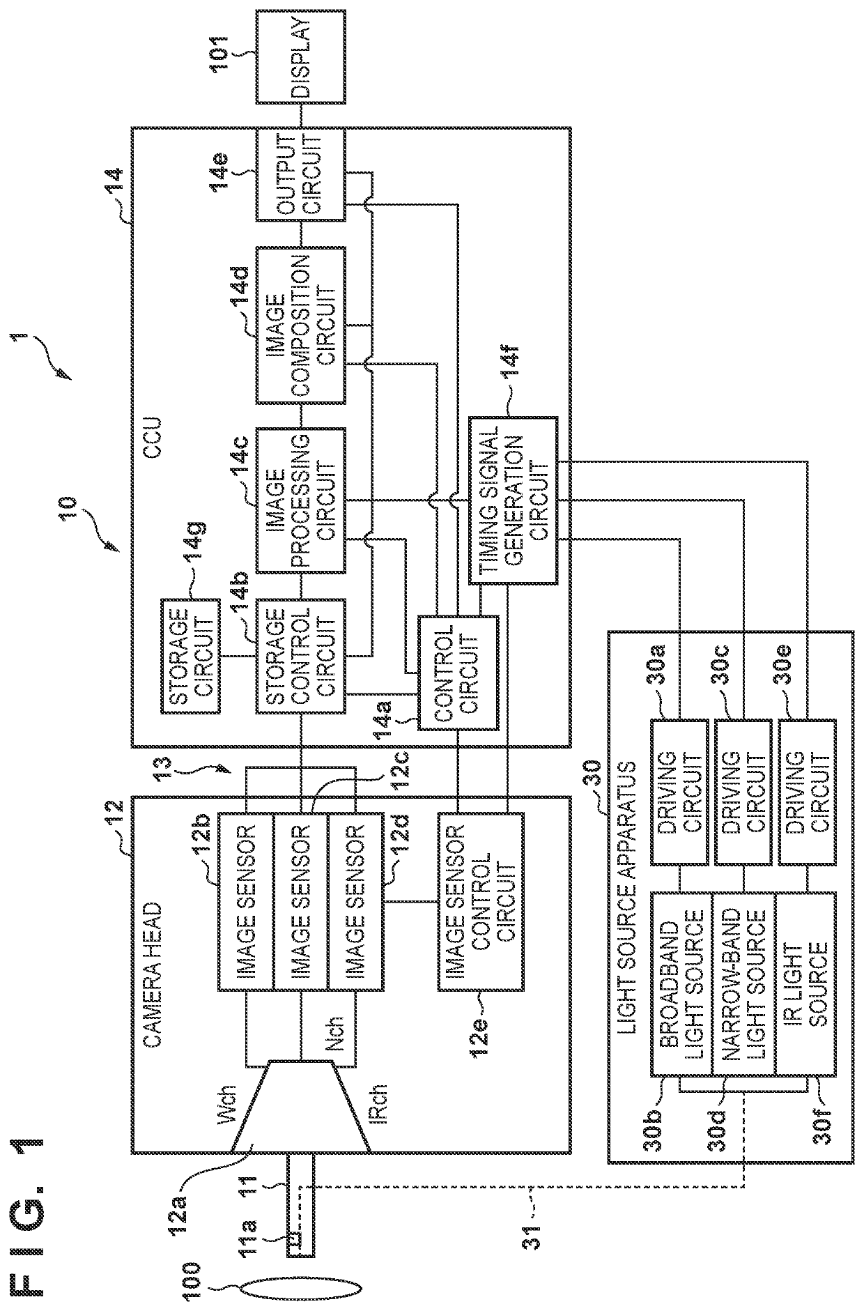
[0012]FIG. 1 is a block diagram showing an example of the configuration of an imaging system 1 including an imaging apparatus 10 according to this embodiment. As shown in FIG. 1, the imaging system 1 according to this embodiment includes the imaging apparatus 10, a light source apparatus 30, and an optical fiber 31.

[0013]The imaging apparatus 10 is used as, for example, a rigid endoscope for a medical application, which is an apparatus that captures the inside of a subject 100. The imaging apparatus 10 includes a scope 11, a camera head 12, a camera cable 13, and a CCU (Camera Control Unit) 14. Note that the imaging apparatus 10 is not limited only to the ri...


PUM

PropertyMeasurementUnit
half-value widthaaaaaaaaaa
wavelength rangeaaaaaaaaaa

Abstract

An imaging apparatus includes an optical element configured to separate incident light into light components in at least two types of wavelength bands. The incident light includes light emitted from a narrow-band light source. At least one light component of the light components in the at least two types of wavelength bands separated by the optical element is light in a narrow band separated by a bandwidth corresponding to a width of a wavelength of the light emitted from the narrow-band light source.

Description

BACKGROUND OF THE INVENTIONField of the Invention[0001]The present disclosure relates to an imaging apparatus.Description of the Related Art[0002]An imaging apparatus, for example, an endoscopic apparatus has conventionally mainly used a CCD (Charge Coupled Apparatus) image sensor. Recently, however, a CMOS (Complementary Metal Oxide Semiconductor) image senor is mainly used because of its advantages such as low cost, single power supply, and low power consumption. As the CMOS image sensor, a rolling shutter method is often employed in general (see Japanese Patent Laid-Open No. 2018-175871).SUMMARY OF THE INVENTION[0003]One of problems to be solved by an embodiment disclosed in this specification is to ensure image quality sufficiently for observation. However, the problem is not limited to this, and obtaining functions and effects derived by configurations shown in an embodiment configured to implement the present invention to be described later can also be defined as another probl...

Claims


Application Information

Patent Timeline
Patent Type & Authority Applications(United States)
IPC IPC(8): G02B27/10G02B27/12
CPCG02B27/1013G02B27/126A61B1/042A61B1/00186A61B1/0638A61B1/00009A61B1/043A61B1/046A61B1/0655
Inventor FUKUMOTO, JUNYA
Owner CANON KK
Why Eureka
Try Eureka