Electric blower and electric vacuum cleaner utilizing the same
A blower, electric motor technology, applied in the direction of engine manufacturing, machine/engine, liquid fuel engine, etc., can solve the problems of air flow loss, the decline of the suction performance of the electric blower 119, etc.
- Summary
- Abstract
- Description
- Claims
- Application Information
AI Technical Summary
Problems solved by technology
Method used
Image

Examples
Embodiment approach 1
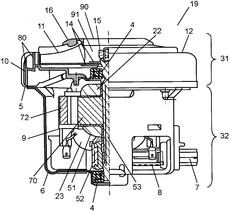
[0029] figure 1 It is a partial sectional view of the side of the electric blower in Embodiment 1. Such as figure 1 As shown, the electric blower 19 includes a motor portion 32 and a fan portion 31 .
[0030] The motor unit 32 has an armature 51 including a shaft 53 , an armature core 70 and a commutator 52 . The armature wire 22 is wound around the outer periphery of the armature core 70 . In addition, the motor unit 32 has the field system 9 in which the field coil 23 is wound around the outer periphery of the field core 72 . Bearings 4 are press-fitted into both ends of the shaft 53 of the armature 51 . One of the bearings 4 is supported by the counter-load side bracket 6 . Moreover, the motor part 32 has the brush holder 7 which contains the carbon brush 8, and is made of metal.
[0031]The fan unit 31 includes: an impeller 11 for sucking in air as a load and blowing out the sucked air; a housing 12 for covering the top of the impeller 11; a load-side bracket 5; an...
Embodiment approach 2
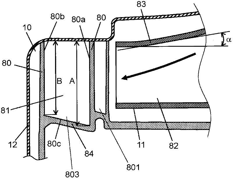
[0040] Figure 4 It is a sectional view of the structure of the impeller and air guide part vicinity of the electric blower in Embodiment 2 of this invention. This embodiment is different from Embodiment 1 in that the shape of the base portion 84, the shape of the flow path bottom surface 80c of the flow path 81, and the inner wall surface 80b of the guide vane 80 on the outer peripheral side are different from those of the first embodiment. The shape and the shape of the connecting portion where the channel bottom surface 80c is connected to the inner wall surface 80b of the guide vane 80 on the outer peripheral side are different. The other configurations are the same as in Embodiment 1, and the same components are assigned the same reference numerals and detailed descriptions thereof are omitted.
[0041] Such as Figure 4 As shown, the flow path bottom surface 80c of the air guide part 10 of this embodiment is a horizontal and flat surface. Here, the horizontal plane is...
Embodiment approach 3
[0044] Figure 5 It is a sectional view of the structure of the impeller and air guide part vicinity of the electric blower in Embodiment 3 of this invention. This embodiment is different from Embodiment 2 in that the shape of the connecting portion where the channel bottom surface 80c is connected to the inner wall surface 80b of the guide vane 80 on the outer peripheral side is different from that in the second embodiment. The other structures are the same as those in Embodiment 2, and the same reference numerals are assigned to the same components, and detailed description thereof will be omitted.
[0045] Such as Figure 5 As shown, in the air guide part 10 of the present embodiment, the connection portion between the flow path bottom surface 80c and the inner wall surface 80b of the guide vane 80 on the outer peripheral side has an arc shape with a radius R. The radius R is the same as the width of the flow path 81 .
[0046] Thus, the length B of the straight portion ...
PUM
 Abstract
Description
Claims
Application Information
 - R&D Engineer
- R&D Manager
- IP Professional
- Industry Leading Data Capabilities
- Powerful AI technology
- Patent DNA Extraction
Browse by: Latest US Patents, China's latest patents, Technical Efficacy Thesaurus, Application Domain, Technology Topic.
© 2024 PatSnap. All rights reserved.Legal|Privacy policy|Modern Slavery Act Transparency Statement|Sitemap