Guide beam device of bar milling machine

A technology for bar rolling mills and beams, applied in the field of guide beam devices for bar mills, can solve problems such as unstable rolling process and loose guide beam devices, and facilitate maintenance and maintenance, reduce production costs, and prepare costs low effect

Inactive Publication Date: 2012-01-11
HEILONGJIANG JIANLONG IRON & STEEL
View PDF6 Cites 6 Cited by
  • Summary
  • Abstract
  • Description
  • Claims
  • Application Information

AI Technical Summary

Problems solved by technology

[0003] The present invention aims to solve the problem that the existing guide beam device used in a bar rolling mill often collides with the guide during the steel rolling process, r

Method used


Image

  • Guide beam device of bar milling machine
  • Guide beam device of bar milling machine
  • Guide beam device of bar milling machine

Examples


specific Embodiment approach 1

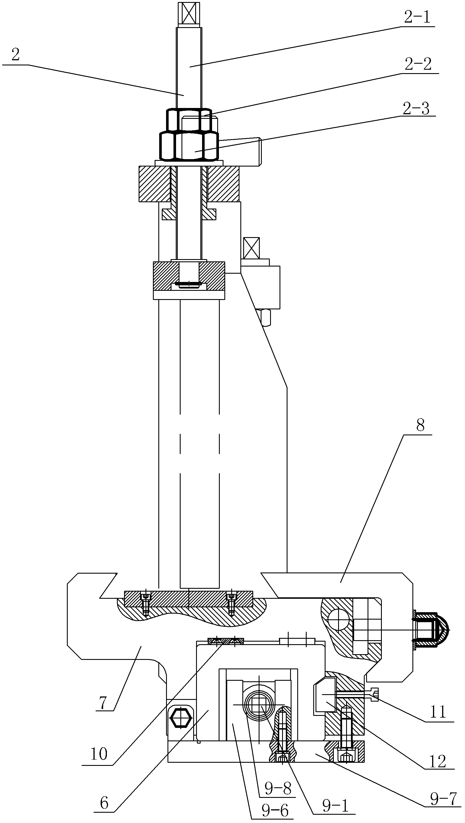
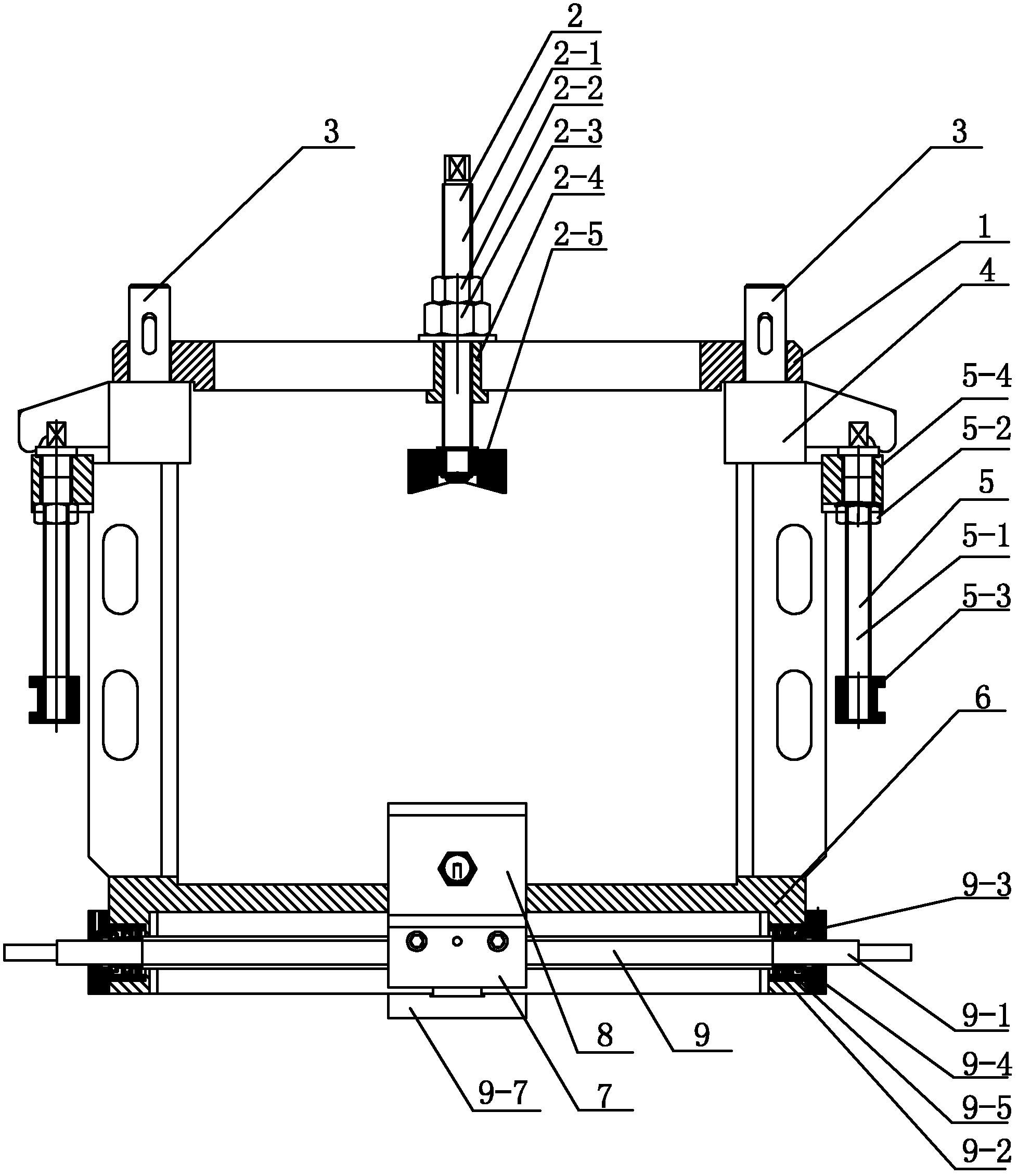
[0007] Specific implementation mode one: combine figure 1 and figure 2 Describe this embodiment, a guide beam device for a bar rolling mill described in this embodiment includes an upper beam 1, a pressing assembly 2, two pull rods 3, two guide brackets 4, a lower beam 6, and a slide rail 7 , splint 8 and sliding lead screw assembly 9, the two ends of described upper beam 1 are respectively connected with the upper end of a pull rod 3, the two ends of described lower beam 6 are respectively connected with the lower end of a pull rod 3, described upper beam 1, The lower beam 6 and the two pull rods 3 constitute a four-frame body, and each guide bracket 4 is respectively set on a pull rod 3, and the two guide brackets 4 can support the upper beam 11 to move up and down along the pull rod 3. The pressing assembly 2 is installed in the middle of the upper beam 1, the lower beam 6 is installed in the groove on the lower surface of the slide rail 7, the splint 8 is installed on th...

specific Embodiment approach 2

[0008] Specific implementation mode two: combination figure 1 This embodiment is described. An adjustment assembly 5 is installed on each pull rod 3 of a guide beam device for a bar rolling mill described in this embodiment, and each adjustment assembly 5 includes an adjustment screw rod 5-1 and a nut 5-2. , adjust the copper block 5-3 and the mounting seat 5-4, the mounting seat 5-4 is fixedly installed on the outer wall of the pull rod 3, and the mounting seat 5-4 is located below the guide bracket 4, the adjusting wire The upper end of the rod 5-1 passes through the mounting base 5-4 and is connected with the guide bracket 4, the nut 5-2 is sleeved on the adjusting screw rod 5-1, and the nut 5-2 is connected to the bottom of the mounting base 5-4. The surface is fixed, and the adjustment copper block 5-3 is sleeved on the lower end of the adjustment screw rod 5-1. Other components and connections are the same as those in the first embodiment.

specific Embodiment approach 3

[0009] Specific implementation mode three: combination figure 1 Describe this embodiment, the compression assembly 2 of a guide beam device for a bar rolling mill described in this embodiment includes a screw rod 2-1, a first nut 2-2, a second nut 2-3, an adjustment sleeve 2-4 and brake block 2-5, the adjustment sleeve 2-4 is inserted in the middle of the upper beam 1, and the lower end of the screw rod 2-1 passes through the adjustment sleeve 2-4 and the brake block 2 -5 connection, the first nut 2-2 and the second nut 2-3 are sequentially set on the screw rod 2-1 from top to bottom, and the first nut 2-2 and the second nut 2-3 are located On the upper surface of the upper beam 1. Other components and connections are the same as those in the first embodiment.


PUM


Abstract

The invention relates to a guide beam device of a bar milling machine, relating to a guide beam device, in particular to the guide beam device of a bar milling machine, aiming to solve the problems of the guide beam device of the existing bar milling machine such as frequent collision of a rolled piece against the guide beam during steel rolling, loosening of each part of the guide beam device and poor stability during rolling. The guide beam device of the bar milling machine comprises an upper crossbeam, a pressing component, two pull bars, two guide brackets, a lower crossbeam, a sliding rail, a clamping plate and a sliding screw component. The two ends of the upper crossbeam are respectively connected with the upper end of one pull bar, the two ends of the lower crossbeam are respectively connected with the lower end of the other pull bar, the guide brackets are respectively sleeved on one pull bar, the pressing component is arranged in the middle of the upper crossbeam, the lower crossbeam is arranged in a groove on the lower surface of the sliding rail, the clamping plate is arranged on the sliding rail, and the sliding screw component is arranged on the lower surface of the lower crossbeam and can drive the sliding rail for linear movement along the upper surface of the lower crossbeam. The guide beam device of the bar milling machine is used for guiding rolled pieces.

Description

technical field [0001] The invention relates to a guide and guard beam device, in particular to a guide and guard beam device for a bar rolling mill. Background technique [0002] The guide beam is an important part of the bar rolling mill, and its main function is to fix the guide. During the rolling process of the existing guide beam device used in the bar rolling mill, the rolled piece often collides with the guide device, resulting in the failure of the guide beam device. All parts are loose, which causes the instability of the rolling process. Contents of the invention [0003] The present invention aims to solve the problem that the existing guide beam device used in a bar rolling mill often collides with the guide during the steel rolling process, resulting in the loosening of various parts of the guide beam device, thereby causing instability in the rolling process, and further proposes a bar Rolling mill guide beam device. [0004] The technical solution adopted...

Claims


Application Information

Patent Timeline
IPC IPC(8): B21B39/14
Inventor 翟长宏戴诗浩赵永明姚本金
Owner HEILONGJIANG JIANLONG IRON & STEEL
Why Eureka
Try Eureka