Device for rotating punching of flat multi-layer goods

A technology of equipment and axis of rotation, applied in the direction of cardboard items, metal processing, etc., can solve problems such as incompatibility between pressure, small adjustment displacement, registration deviation, etc.

Inactive Publication Date: 2012-01-11
GALLUS DRUCKMASCHINEN GMBH
View PDF15 Cites 0 Cited by
  • Summary
  • Abstract
  • Description
  • Claims
  • Application Information

AI Technical Summary

Problems solved by technology

[0012] A disadvantage of the described device for punching, which allows the distance of the punching cylinder to be adjusted from the counterpart punching cylinder, is that only small adjustment displacements are allowed here
It is therefore not possible to press the two cylinders away from each other to such an extent that the press register adjustment is allowed
A further disadvantage is that the adjustment of the distance between two cylinders is often accompanied by a small lateral movement of at least one cylinder, which causes register deviations

Method used


Image

  • Device for rotating punching of flat multi-layer goods
  • Device for rotating punching of flat multi-layer goods
  • Device for rotating punching of flat multi-layer goods

Examples


Embodiment Construction

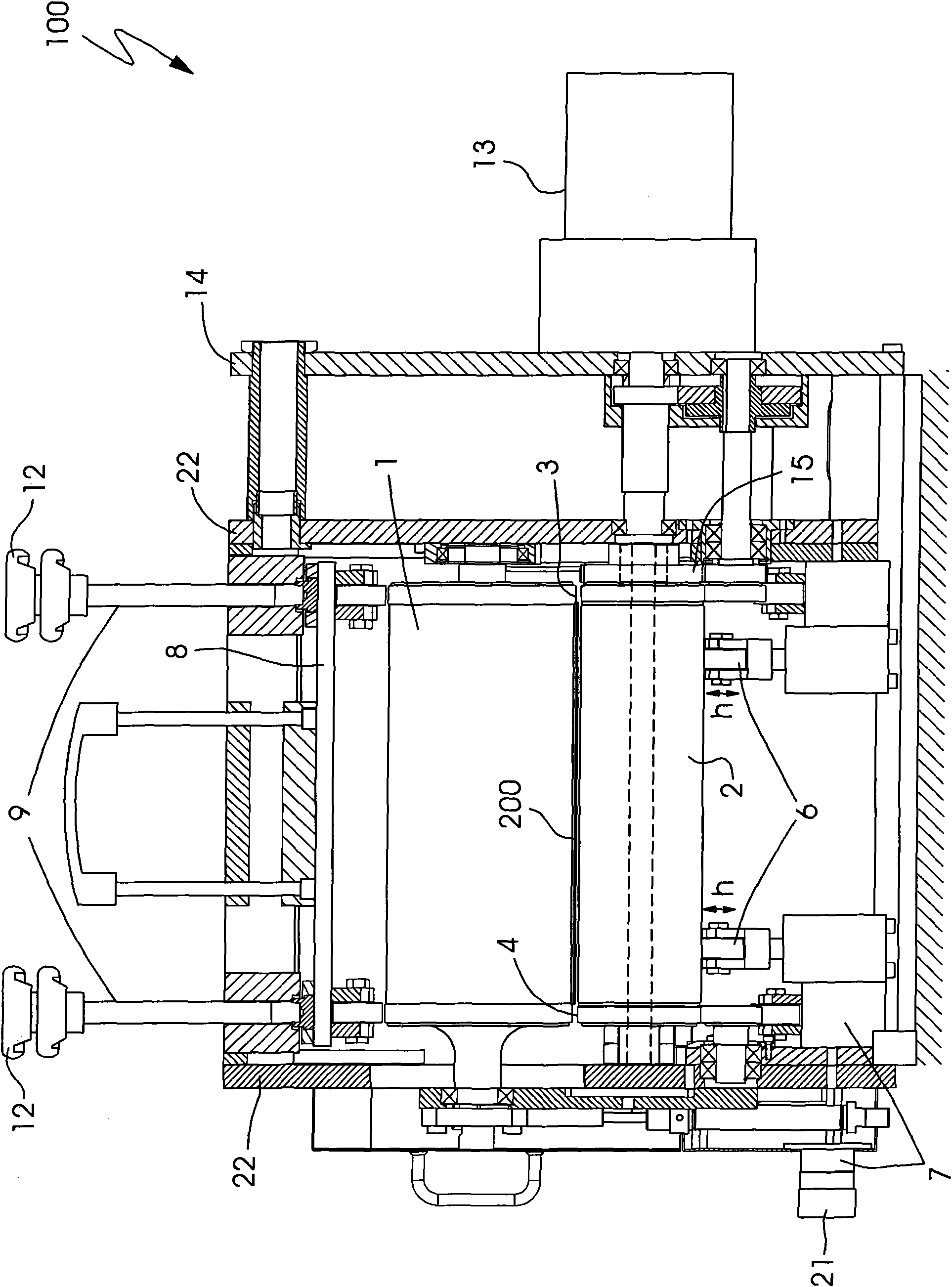
[0029] figure 1A schematic view of an apparatus 100 for punching according to the invention is shown, which is also called a punching apparatus or a rotary punch. The device for stamping has a stamping cylinder 1 and a counterpressing cylinder 2 , between which a printing material 200 is conveyed and subjected to stamping. The stamping cylinder 1 and the counterpressing cylinder 2 are mounted rotatably in a side wall 22 of the stamping device 100 . Roller pillows 3, 4 are assigned to these rollers 1, 2, respectively. The stamping cylinder 1 thus has a rolling pillow 3 at its two outer ends. Roller pillows 4 are arranged on the right and left sides of the mating stamping cylinder 2 . The rollers 3 assigned to the stamping cylinder and the rollers 4 assigned to the mating stamping roller roll on each other. The force take-up of the stamping force from the stamping cylinder 1 takes place via the rollers 4 via the rollers 3 of the stamping cylinder 1 . The position of the sta...


PUM


Abstract

The invention relates to a device for rotating punching of flat multi-layer goods, and particularly relates to a diecutting device (100), in particular for cutting labels, includes a diecutting cylinder (1) that rotates about an axis of rotation, a counterpressure cylinder that rotates about an axis of rotation essentially parallel to the axis of rotation of the diecutting cylinder (1) and has a cylinder body, and bearer rings (3, 4) assigned to the cylinders and rolling off on each other. A spacing between the diecutting cylinder (1) and the counterpressure cylinder (2) is adjustable. A respective bearer ring (4) assigned to the counterpressure cylinder (2) is connected to a counterpressure cylinder shaft (16) and each end of the cylinder body (11) of the counterpressure cylinder (2) is connected to the counterpressure cylinder shaft (16) by a respective connecting link guide (5, 10).

Description

technical field [0001] The invention relates to an apparatus for rotary stamping of flat multilayer articles, in particular to an apparatus for stamping, in particular for stamping labels, having a stamping cylinder rotatable about a rotation axis and capable of rotating around a Cooperating punching cylinders that rotate with their axes of rotation substantially parallel to their axes of rotation, the cooperating punching cylinders have a cylinder body, wherein the two cylinders are assigned bearings that roll on each other, between the punching cylinder and the counterpressing cylinder The distance between them can be adjusted. Background technique [0002] The apparatus is used for punching flat multi-layered articles and comprises a punching roll and a mating punching roll. At least one layer of the flat multilayer article can be punched through in the punching gap formed by the punching drum and the counter punching drum without cutting through all the layers, wherein ...

Claims


Application Information

Patent Timeline
Patent Type & Authority Applications(China)
IPC IPC(8): B26F1/20B26F1/38B31D1/02
CPCB26D7/265B26D7/2628
Inventor T・德曼德
Owner GALLUS DRUCKMASCHINEN GMBH
Why Eureka
Try Eureka