Gear rack type self-locking rope clip

A rack-and-pinion and cable-holding device technology, which is applied in the field of automobile crash test devices, can solve problems such as troublesome operation, complex structure, and small locking force

Inactive Publication Date: 2012-01-18
HUNAN UNIV
View PDF5 Cites 5 Cited by
  • Summary
  • Abstract
  • Description
  • Claims
  • Application Information

AI Technical Summary

Problems solved by technology

[0002] At present, the grips used in domestic automobile crash tests can be divided into two types: fixed type and trailer type; fixed type grips are always connected with the traction rope from the beginning to the end of the collision test, which cannot realize the cycle of the collision line, and the operation is troublesome
Moreover, the tension between the fixed rope grip and the traction rope is too large at the moment of collision, which is easy to cause accidents; for the traditional tow-type grip rope, the collision line can be realized, but its structure is complicated, and the grip force is also affected by its structure. In the currently known locking methods, the eccentric cam locking method is widely used in various locking mechanisms due to its simple structure, fast locking and self-locking characteristics of the eccentric cam. Small locking force and low reliability

Method used


Image

  • Gear rack type self-locking rope clip
  • Gear rack type self-locking rope clip
  • Gear rack type self-locking rope clip

Examples


Embodiment 1

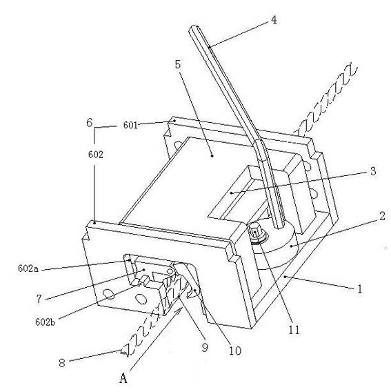
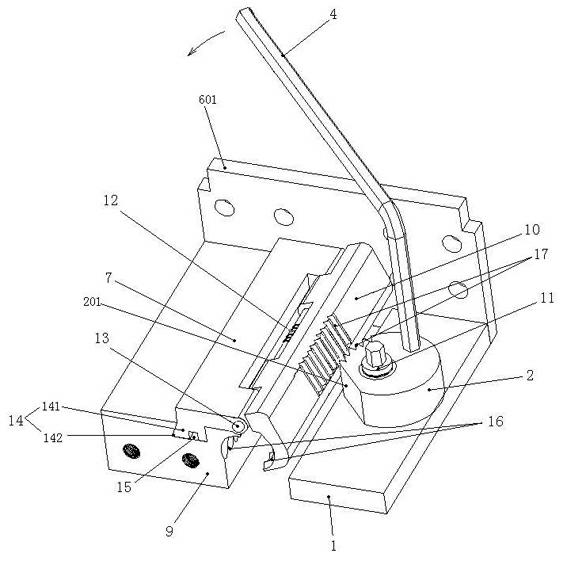
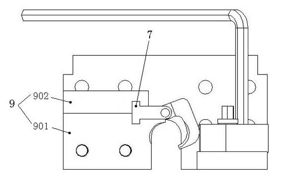
[0015] See figure 1 , figure 2 , the rack and pinion type self-locking grip rope device, including a base, the base includes a left base 9 and a right base 1, and the left and right bases 9, 1 are connected together to form an integral connection plate 6; the connection plate 6 is divided into upper and lower connections Plates 601, 602; a through opening A is formed between the left and right bases 9 and 1 bottoms, and the left base 9 on one side along the direction of the through opening A is provided with a hinge slider 7 sliding in this direction; the hinge slider 7 and The left base 9 is connected by a dovetail rail chute structure 14, the left base 9 is provided with a dovetail groove 14, and the bottom of the hinge slider 7 is provided with a dovetail slide rail 141 to cooperate with the dovetail groove 141 on the left base 9; the hinge slider The dovetail slide rail 141 of 7 is provided with a limit hole 15; the hinge slider 7 is hinged with a long pin 13 to have a m...


PUM


Abstract

The invention discloses a gear rack type self-locking rope clip. The gear rack type self-locking rope clip comprises a base, wherein a through opening is formed at the bottom of the base; one side of the base along the direction of the through opening is provided with a hinge slide block sliding along the direction; a movable claw tile corresponding to the through opening is hinged on the hinge slide block; one part forming the through opening on the base provided with the hinge slide block is used as a fixed claw tile and forms a rope clipping part together with the movable claw tile; an eccentric cam matched with the movable claw tile through teeth is arranged on the base positioned on the other side of the through opening; and a handle is arranged on the eccentric wheel. The gear rack type self-locking rope clip disclosed by the invention has the advantages of manual pre-clamping and automatic locking functions, simple structure, large rope clipping force, safety, reliability and the like.

Description

technical field [0001] The invention belongs to an automobile collision test device, in particular to a rack and pinion self-locking gripping device. Background technique [0002] At present, the grips used in domestic automobile crash tests can be divided into two types: fixed type and trailer type; fixed type grips are always connected with the traction rope from the beginning to the end of the collision test, which cannot realize the cycle of the collision line, and the operation is troublesome . Moreover, the tension between the fixed rope grip and the traction rope is too large at the moment of collision, which is easy to cause accidents; for the traditional tow-type grip rope, the collision line can be realized, but its structure is complicated, and the grip force is also affected by its structure. In the currently known locking methods, the eccentric cam locking method is widely used in various locking mechanisms due to its simple structure, fast locking and self-loc...

Claims


Application Information

Patent Timeline
Patent Type & Authority Applications(China)
IPC IPC(8): G01M7/08
Inventor 毛建中钟盼希王路翔颜世强钟志华
Owner HUNAN UNIV
Why Eureka
Try Eureka