Busbar assembly device, busbar self-piercing riveting system and busbar assembly method

An assembly device and assembly method technology, applied in the direction of electrical components, circuits, cables/conductors, etc., can solve the problems of low assembly accuracy, troublesome calibration and adjustment of subsequent processes, and high labor intensity of operation, so as to improve assembly accuracy and assembly Efficiency, meeting the requirements of automated production lines, and reducing labor intensity

Active Publication Date: 2013-11-13
成方泳
View PDF5 Cites 0 Cited by
  • Summary
  • Abstract
  • Description
  • Claims
  • Application Information

AI Technical Summary

Problems solved by technology

However, the existing busbar assembly methods are usually done manually or with simple auxiliary tools. Therefore, it may lead to low assembly accuracy, the positional relationship of the busbar components and the dimensional tolerance deviation of the overall structure of the busbar. Large size and low assembly efficiency
In addition, the existing assembly methods also have disadvantages such as high labor intensity, low production efficiency, and inability to meet the requirements of automated production lines.
[0005] In addition, the axis offset of the busbar after assembly will also bring great trouble to the calibration and adjustment of the subsequent process
In addition, the uniformity, stability and accuracy of the bonding between the various parts of the busbar cannot be guaranteed when the clamps are used to fix the various parts of the busbar after assembly, so the repeatability is low, resulting in large differences between different busbars, and thus cannot Provide accurate basis for accurate measurement of busbar peripheral dimensions

Method used


Image

  • Busbar assembly device, busbar self-piercing riveting system and busbar assembly method
  • Busbar assembly device, busbar self-piercing riveting system and busbar assembly method
  • Busbar assembly device, busbar self-piercing riveting system and busbar assembly method

Examples


Embodiment Construction

[0048] In the following description, numerous specific details are given in order to provide a more thorough understanding of the present invention. It will be apparent, however, to one skilled in the art that the present invention may be practiced without one or more of these details. In other examples, some technical features known in the art are not described in order to avoid confusion with the present invention.

[0049] In order to provide a thorough understanding of the present invention, the detailed structure will be set forth in the following description. It is evident that the practice of the invention is not limited to specific details familiar to those skilled in the art. Preferred embodiments of the present invention are described in detail below, however, the present invention may have other embodiments besides these detailed descriptions.

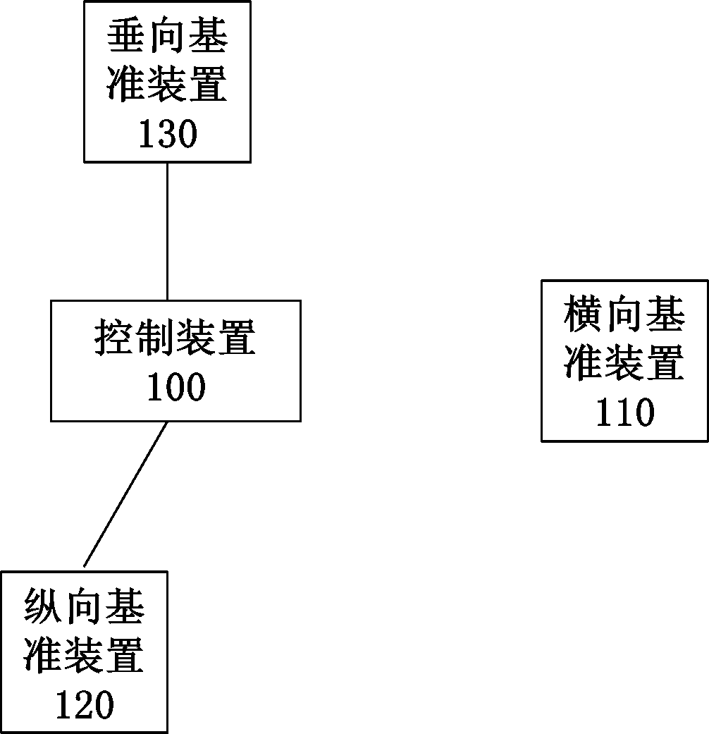
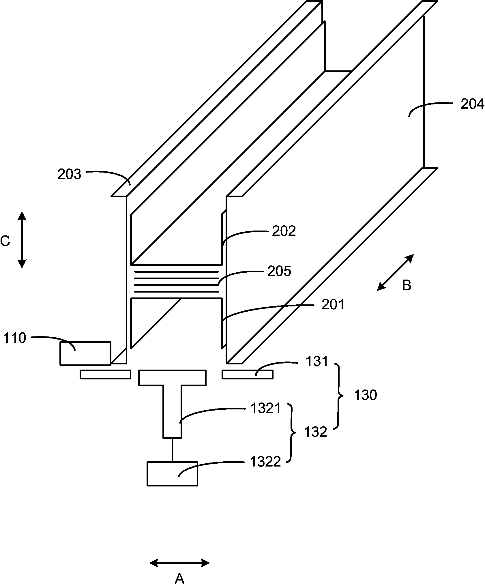
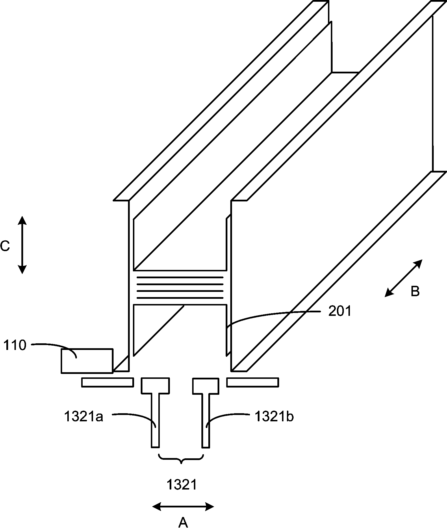
[0050] According to one aspect of the present invention, a busbar assembly device is provided. The bus bar assembly dev...


PUM


Abstract

The invention discloses a busbar assembly device, a busbar self-piercing riveting system and a busbar assembly method. The busbar assembly device comprises a control device, a transverse reference device, a longitudinal reference device and a vertical reference device, wherein the control device is used for acquiring the parameter information of a busbar to be assembled and forming a control signal; the transverse reference device is used for providing a transverse reference of the busbar to be assembled; the longitudinal reference device is used for providing a longitudinal reference of the busbar to be assembled; the vertical reference device is used for providing a vertical reference of the busbar to be assembled; and the control device controls at least one of the transverse reference device, the longitudinal reference device and the vertical reference device according to the control signal and provides the transverse reference, the longitudinal reference and the vertical reference for the busbar to be assembled. In the busbar assembly device, the parameter information of the busbar to be assembled is acquired by using the control device, the control signal is formed, and the transverse reference, the longitudinal reference and the vertical reference, which are matched, are provided for the busbar to be assembled, so assembly accuracy and assembly efficiency can be improved, and the position relation between all parts of the busbar and the dimensional tolerance of the overall structure of the busbar are guaranteed.

Description

technical field [0001] The invention relates to the field of bus bar manufacturing, in particular to a bus bar assembly device, a bus bar self-piercing riveting system and a bus bar assembly method. Background technique [0002] As a new type of distribution wire, the busbar has emerged as the times require. Compared with traditional cables, it fully demonstrates its superiority in the transmission of large currents. It is especially suitable for low-voltage power distribution systems in industrial plants, mines, etc., and high-rise commercial and residential buildings. , hotels, hospitals and other power supply systems. [0003] The bus bar (busbar) is composed of a metal protective shell, a conductive bar, insulating materials and related accessories. The metal protective shell mainly includes H profiles on both sides (including the first H profile and the second H profile) and between the H profiles. Between U profiles (including the upper U profile and the lower U profi...

Claims


Application Information

Patent Timeline
Patent Type & Authority Patents(China)
IPC IPC(8): H01B13/00H01B13/22
Inventor 成方泳
Owner 成方泳
Why Eureka
Try Eureka