Inflation expansion truss solar panel array capable of on-orbit assembly

A technology of inflatable deployment and solar panels, applied in electrical components, photovoltaic power generation, photovoltaic modules, etc., can solve the problems of difficult launch and on-orbit installation, poor deployment reliability, large launch volume, etc., to facilitate space assembly and expansion, Easy to install on rails, small folded volume

Inactive Publication Date: 2012-01-18
HARBIN INST OF TECH
View PDF6 Cites 6 Cited by
  • Summary
  • Abstract
  • Description
  • Claims
  • Application Information

AI Technical Summary

Problems solved by technology

[0005] The purpose of the present invention is to solve the problems of complex structure, easy failure, poor deployment reliability, heavy overall weight, low folding efficiency, large launch volume, difficulty in launch and on-orbit installation of mechanical unfolded solar panels in use, and at the same time Solve the problem that the structural stiffness and fundamental frequency decrease with the increase of the structural size due to the use of large-area solar panels, which may easily cause resonance with the main body of the aircraft and make it difficult to control the attitude of the aircraft, and then provide an inflatable deployment that can be assembled on orbit Truss solar panel array

Method used


Image

  • Inflation expansion truss solar panel array capable of on-orbit assembly
  • Inflation expansion truss solar panel array capable of on-orbit assembly
  • Inflation expansion truss solar panel array capable of on-orbit assembly

Examples


specific Embodiment approach 1

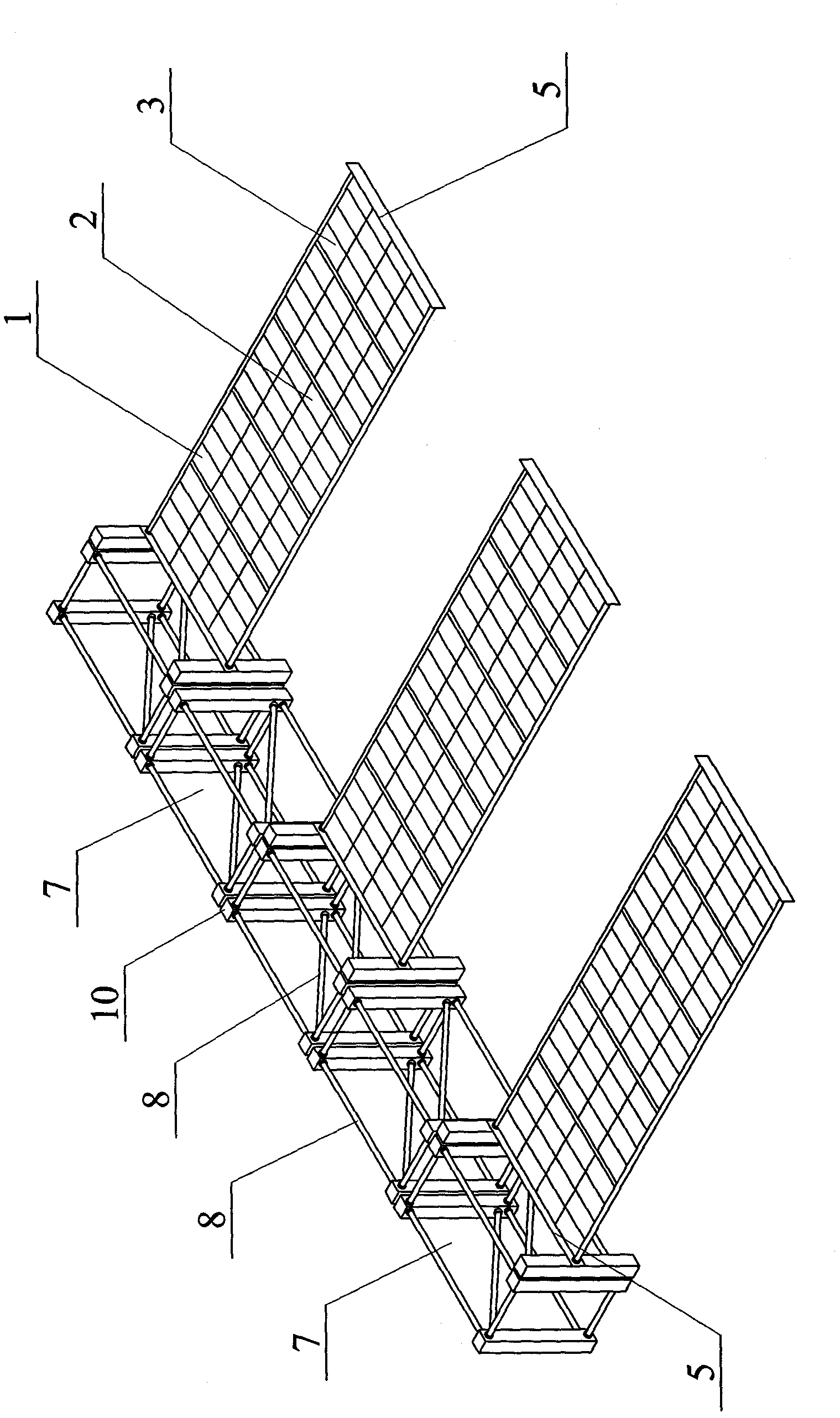
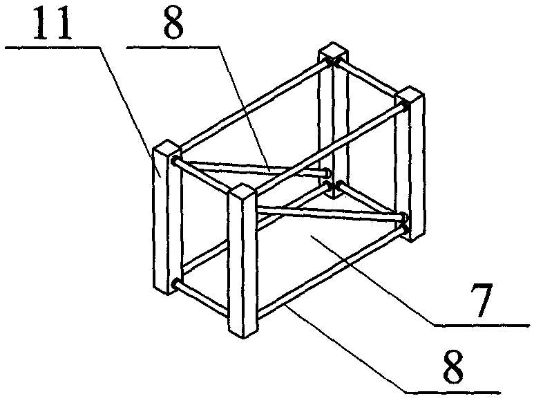
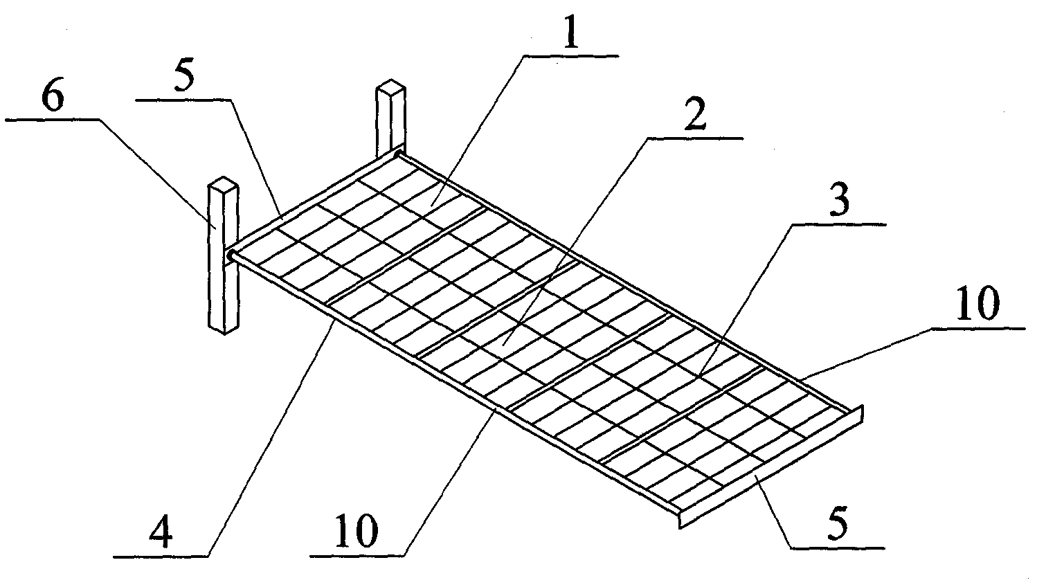
[0027] Specific implementation mode one: see Figure 1-Figure 3, an inflatable and deployable truss-type solar panel array that can be assembled on rail in this embodiment includes a plurality of assembled inflatable and deployable solar panel units 1 and a plurality of assembled inflatable and deployable truss units 7; each assembled inflatable and deployable The solar panel unit 1 is composed of an assembled inflatable unfolding frame unit 4, at least two solar cell substrates 2 and a plurality of solar cell sheets 3, and the at least two solar cell substrates 2 are installed on the assembled inflatable unfolding frame unit 4 Above, each solar cell substrate 2 is pasted with a plurality of solar cell sheets 3; each assembled inflatable frame unit 4 is composed of two inflatable frame unit support tubes 10, two horizontal plates 5 and two frame unit connecting columns 6 structure, two inflatable frame unit support tubes 10 and two horizontal plates 5 form a quadrilateral fram...

specific Embodiment approach 2

[0029] Specific implementation mode two: see image 3 , the specific embodiment 1 describes an inflatable unfolded truss-type solar panel array that can be assembled on rails, and the number of solar cell substrates 2 is five.

specific Embodiment approach 3

[0030] Specific implementation mode three: see figure 1 , a specific embodiment of a kind of on-rail assembled inflatable deployment truss solar panel array, the number of assembled inflatable deployment solar panel units 1 is three, and the number of assembled inflatable deployment truss units 7 is five indivual.


PUM


Abstract

The invention provides an inflation expansion truss solar panel array capable of on-orbit assembly. The invention relates to an inflation expansion truss solar panel array to solve a problem that a present solar panel can not satisfy a large area solar panel requirement of spacecrafts such as a satellite, a space station and the like. Technical schemes of the invention are as follows: firstly, along a vertical equal interval, an assembly inflation expansion vertical truss is provided with a plurality of assembly inflation expansion solar panel units which are in mortise-tenon connection with truss unit connection columns of an assembly inflation expansion truss unit through framework unit connection columns; secondly, along a vertical direction, the assembly inflation expansion vertical truss is provided with a plurality of the assembly inflation expansion solar panel units; thirdly, one end of an assembly inflation expansion transverse truss is aligned with one end of the assembly inflation expansion vertical truss, and is in mortise-tenon connection with the truss unit connection columns through the framework unit connection columns. The inflation expansion truss solar panel array is applied to an astronaut on-orbit assembly inflation expansion truss solar panel array.

Description

technical field [0001] The invention relates to an inflatable and unfolded truss type solar panel array. Background technique [0002] With the development of space station technology, satellites, space stations and other spacecraft need to have a greater power supply, which requires a larger area of ​​solar panels. [0003] Existing solar panels mainly adopt the structural form of mechanically unfolded solar panels. The mechanical unfolding support structure is composed of many rigid components connected by a connecting mechanism, a control unfolding mechanism, and a locking mechanism. In use, there are complex structures, easy failures, poor deployment reliability, heavy overall weight, low folding efficiency, and launch volume. Large and other problems; due to the increase in the structural size of the sail panel, its launch volume has increased significantly, making it difficult or even impossible to launch spacecraft such as satellites or space stations; due to the lar...

Claims


Application Information

Patent Timeline
Patent Type & Authority Applications(China)
IPC IPC(8): H01L31/042H01L31/045H02S30/20
CPCY02E10/50
Inventor 苗常青刘畅林国昌杜星文
Owner HARBIN INST OF TECH
Why Eureka
Try Eureka