
Erosion indicator for compressor wheel

A centrifugal compressor and compression stage technology, applied in the field of turbine compression stage, can solve the problems of thin erosion shape, hard to see, difficult to quickly determine the erosion amount, etc.

Active Publication Date: 2012-01-18
TURBOMECA SA
View PDF6 Cites 3 Cited by
  • Summary
  • Abstract
  • Description
  • Claims
  • Application Information

AI Technical Summary

Problems solved by technology

[0009] Often, the erosion profile is thin and difficult to see, making it difficult to quickly determine whether the amount of erosion that has occurred is acceptable

Method used


Image

  • Erosion indicator for compressor wheel
  • Erosion indicator for compressor wheel
  • Erosion indicator for compressor wheel

Examples


Embodiment Construction

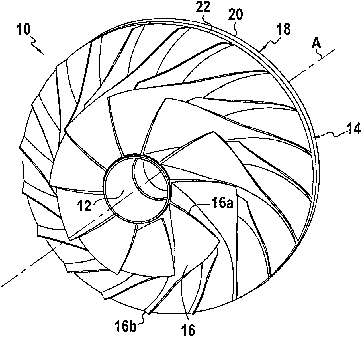
[0043] figure 1 is a perspective view of a compressor wheel 10 of the type commonly found in helicopter gas turbines. Naturally, the invention is also applicable to other types of turbine engines comprising a compressor wheel.

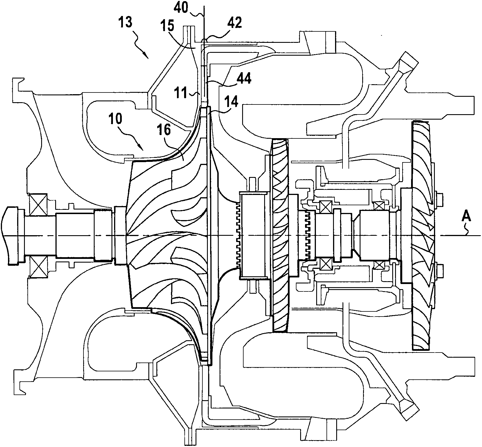
[0044] In known manner, the compressor wheel 10 comprises a hub 12 intended to cooperate with a drive shaft (not shown) to drive the wheel 10 in rotation about its axis A. As shown in FIG. In the following description, the adjectives "radial" and "axial" are used with respect to the axis A. The compressor wheel 10 is mounted in the housing so as to face the diffuser 11 of the compression stage 13, which in Figure 7 visible in .

[0045] The compressor wheel 10 also includes webs 14, where figure 2 As can be seen more clearly in , the web extends radially from the hub 12 .

[0046] Furthermore, the compressor wheel 10 carries a plurality of blades 16 each extending between a leading edge 16a and a trailing edge 16b. These blades 16 are also know...


PUM


Abstract

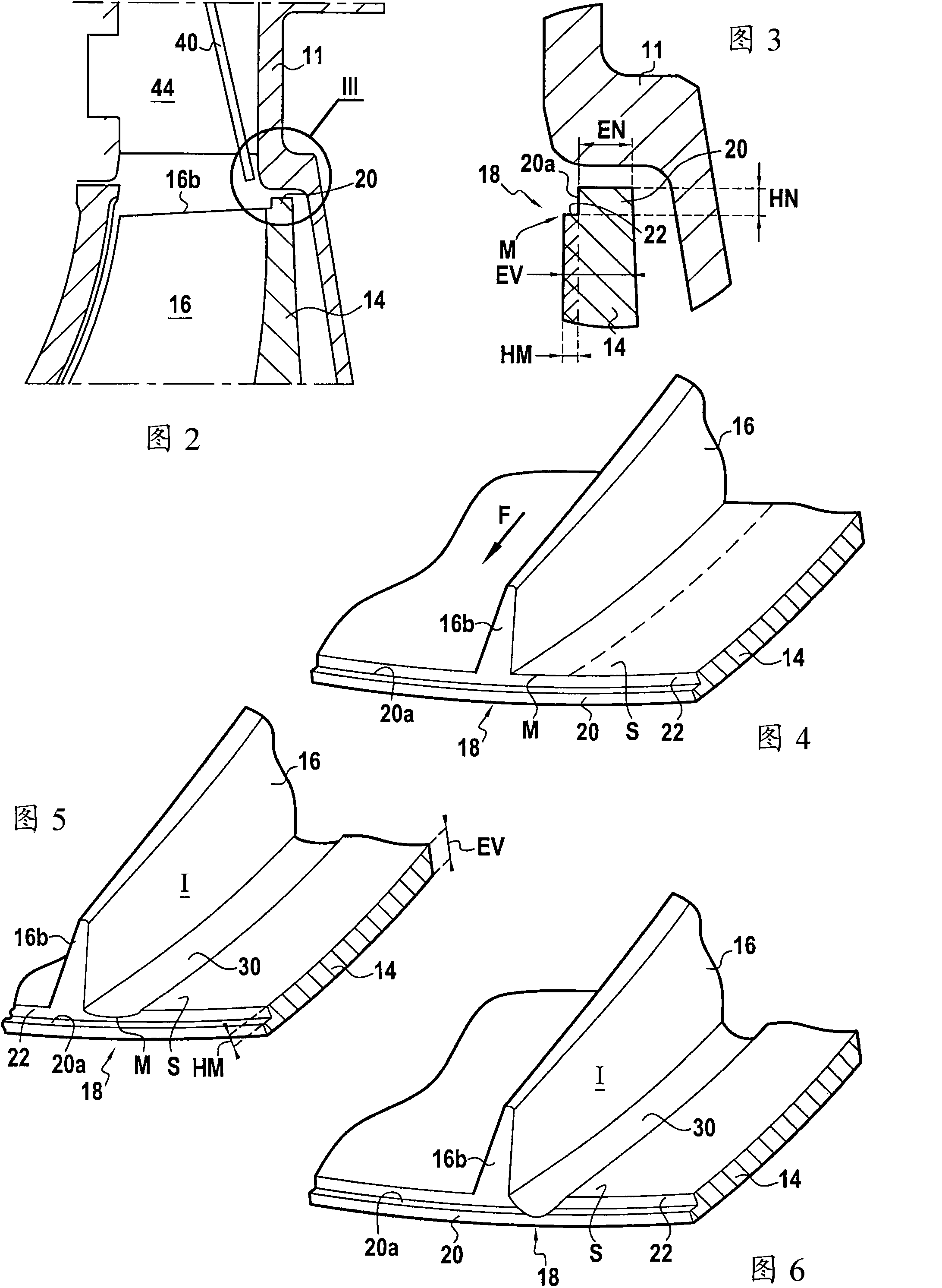
The invention relates to a centrifugal compressor wheel (10) that comprises a hub (12), a web (14) radially extending from the hub and supporting a plurality of blades (16). The invention is characterized in that the web includes a wheel erosion indicator (18).

Description

technical field [0001] The present invention relates to the field of turbomachine compression stages such as, but not limited to, aircraft turbine engines, and in particular the invention relates to the problem of wear of the elements making up such compression stages. [0002] More precisely, the invention concerns one of its constituent elements, a centrifugal compressor wheel comprising a hub, a web extending radially from said hub, and a plurality of blades carried by said wheel. [0003] In the following, the adjectives "axial" and "radial" are identified relative to the axis of rotation of the compressor wheel. Background technique [0004] Such known centrifugal compressor wheels cooperate with radial diffusers to compress the air entering the compression stage axially before it exits radially. [0005] In known manner, each vane extends from a front edge to a rear edge and it has a pressure side and a suction side. [0006] While working in the compression stages, ...

Claims


Application Information

Patent Timeline
Patent Type & Authority Applications(China)
IPC IPC(8): F04D29/28
CPCF04D29/289F04D27/001F04D29/284F05D2260/80F04D17/08F04D29/30
Inventor 杰弗洛伊·比罗蒂奥利维耶·戴斯奎布斯西拉维·古尔丹特奥利维耶·托特
Owner TURBOMECA SA
Learn More