
Auxiliary device capable of paying off cable from top to bottom in building construction and cable paying off method

An auxiliary device and building construction technology, applied in the direction of cable laying equipment, the use of reel/photosensitive drum arrangement, etc., can solve the problems of slow cable drop, cable injury, difficult cable weight and speed control, etc., to achieve The effect of safe setting-out process and reduction of construction safety hazards

Active Publication Date: 2012-01-25
中建五局安装工程有限公司
View PDF3 Cites 6 Cited by
  • Summary
  • Abstract
  • Description
  • Claims
  • Application Information

AI Technical Summary

Problems solved by technology

At present, the cable from top to bottom relies on the gravity of the cable itself to achieve self-falling, but there is a big problem in this method of falling by gravity: as the weight of the cable drops continues to increase, if no intervention is made, the cable will fall. The speed will be faster and faster, so the more you go to the back, the more difficult it is to control the cable (because the weight and speed of the cable are increasing), which undoubtedly requires more construction workers to drag the cable together to overcome the gravity of the cable and make the cable It can fall slowly, and once the speed is out of control, serious safety accidents such as cable injuries may occur

Method used


Image

  • Auxiliary device capable of paying off cable from top to bottom in building construction and cable paying off method
  • Auxiliary device capable of paying off cable from top to bottom in building construction and cable paying off method
  • Auxiliary device capable of paying off cable from top to bottom in building construction and cable paying off method

Examples


Embodiment Construction

[0021] The present invention will be further described below in conjunction with accompanying drawing.

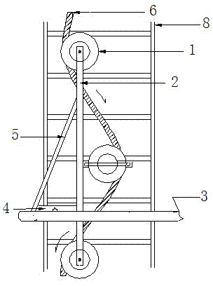
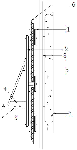
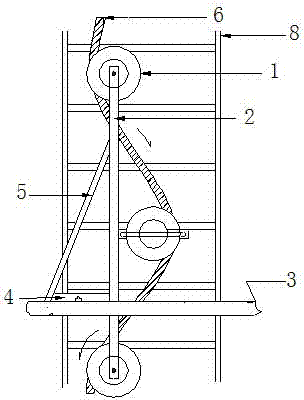
[0022] see figure 1 and figure 2 , as can be seen from the figure, the auxiliary device for laying down cables from top to bottom in the building construction of the present invention includes at least three fixed pulleys 1, and the fixed pulleys 1 are fixedly installed on the vertical poles 2 and are at different heights respectively. The fixed pulleys 1 are located on the same vertical surface; at least one fixed pulley 1 can be adjusted left and right relative to the vertical pole 2 to change the horizontal distance between the fixed pulley and the adjacent fixed pulley (there are many adjustment methods to realize this function : For example, the fixed pulley is connected with the vertical pole through a cross bar, and there is a chute on the cross bar, and the fixed pulley can move left and right along the chute, at this time, the position of the cross bar and the ve...


PUM


Abstract

The invention discloses an auxiliary device capable of paying off a cable from top to bottom in building construction and a cable paying off method. The auxiliary device comprises at least three fixed pulleys, the fixed pulleys are fixedly arranged on a vertical strut and are respectively located at different heights, at least one fixed pulley can be regulated left and right relative to the vertical strut; and a horizontal cross rod is arranged on the vertical strut, and an inclined pull rod is arranged between the other end of the horizontal cross rod and the vertical strut. The cable paying off method disclosed by the invention comprises the following steps of: (1) fixing the auxiliary device on a floor slab, and mounting the vertical strut in a wire hole; and (2) enabling one end of the cable to round all the fixed pulleys from top to bottom, then starting paying off, regulating the fixed pulley which can be regulated at left and right as required in a cable paying off process to change horizontal distance between the fixed pulley and adjacent fixed pulleys, thus paying off speed of the cable can be controlled. According to the invention, labour is saved in the cable paying off process, a falling speed is easy to control, the whole cable paying off process is very safe, and potential safety hazards in construction are reduced.

Description

technical field [0001] The invention relates to a cable pay-off technology, in particular to an auxiliary device for laying down cables from top to bottom in building construction. The present invention also relates to a method for lowering cables from above using the auxiliary device. [0002] Background technique [0003] In the construction of medium and high-rise and super high-rise buildings, the direction and laying of cables is an important project. Usually the cables are first routed up and down along the wall and shaft, and then laid to the corresponding floors according to the design, and then laid on each floor. For the wiring in the up and down direction, the way of laying out the wires from top to bottom is often adopted. There is a wire hole on each floor where the cable passes. After the cable is laid in place, the hole is sealed for fire protection. A ladder frame is arranged on the wall, and the cables in the up and down direction are fixed on the ladder ...

Claims


Application Information

Patent Timeline
IPC IPC(8): H02G1/06H02G11/02
Inventor 朱祥彭辉
Owner 中建五局安装工程有限公司
Learn More