Dual-drive horizontal dual-purpose pay-off device

A pay-off device and dual-drive technology, applied in the field of dual-drive horizontal dual-purpose pay-off devices, can solve the problems of cable damage, inability to adapt to different sizes, and reduced pay-off efficiency, so as to achieve a safe and good pay-off process. Support effect, effect of reducing damage rate

Active Publication Date: 2022-03-04
无锡广盈集团有限公司
View PDF10 Cites 0 Cited by
  • Summary
  • Abstract
  • Description
  • Claims
  • Application Information

AI Technical Summary

Problems solved by technology

[0003] When laying cables, it is necessary to pay out the cables on the cable reel and pull them for laying. The current cable pay-off device basically lays cables in a semi-automatic form, which cannot be applied to cable reels of different sizes. When the cable reel When the size changes, it is necessary to manually replace the tray frame, resulting in a decrease in the efficiency of the cable release, and the existing cable release device cannot perform the cable release operation and stable support when the cable tray is defective, which may cause damage to the cable. The safety and applicability are reduced, and at the same time, the existing cable pay-off device cannot complete the pay-off work when the drive components are powered off
[0004] Therefore, the invention can be applied to cable reels of different sizes, can still perform unwinding operations and provide stable support when the cable reel has defects, and can perform manual unwinding in a power-off state. It is very necessary to solve the problems that the above-mentioned prior art cannot be applied to cable reels of different sizes, and cannot perform unwinding operation and stable support when the cable reel has defects, and cannot complete unwinding when the power is cut off.

Method used


Image

  • Dual-drive horizontal dual-purpose pay-off device
  • Dual-drive horizontal dual-purpose pay-off device
  • Dual-drive horizontal dual-purpose pay-off device

Examples


Embodiment 1

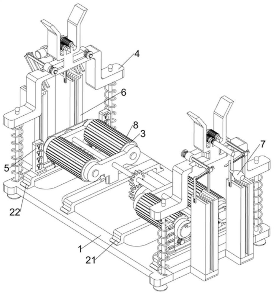
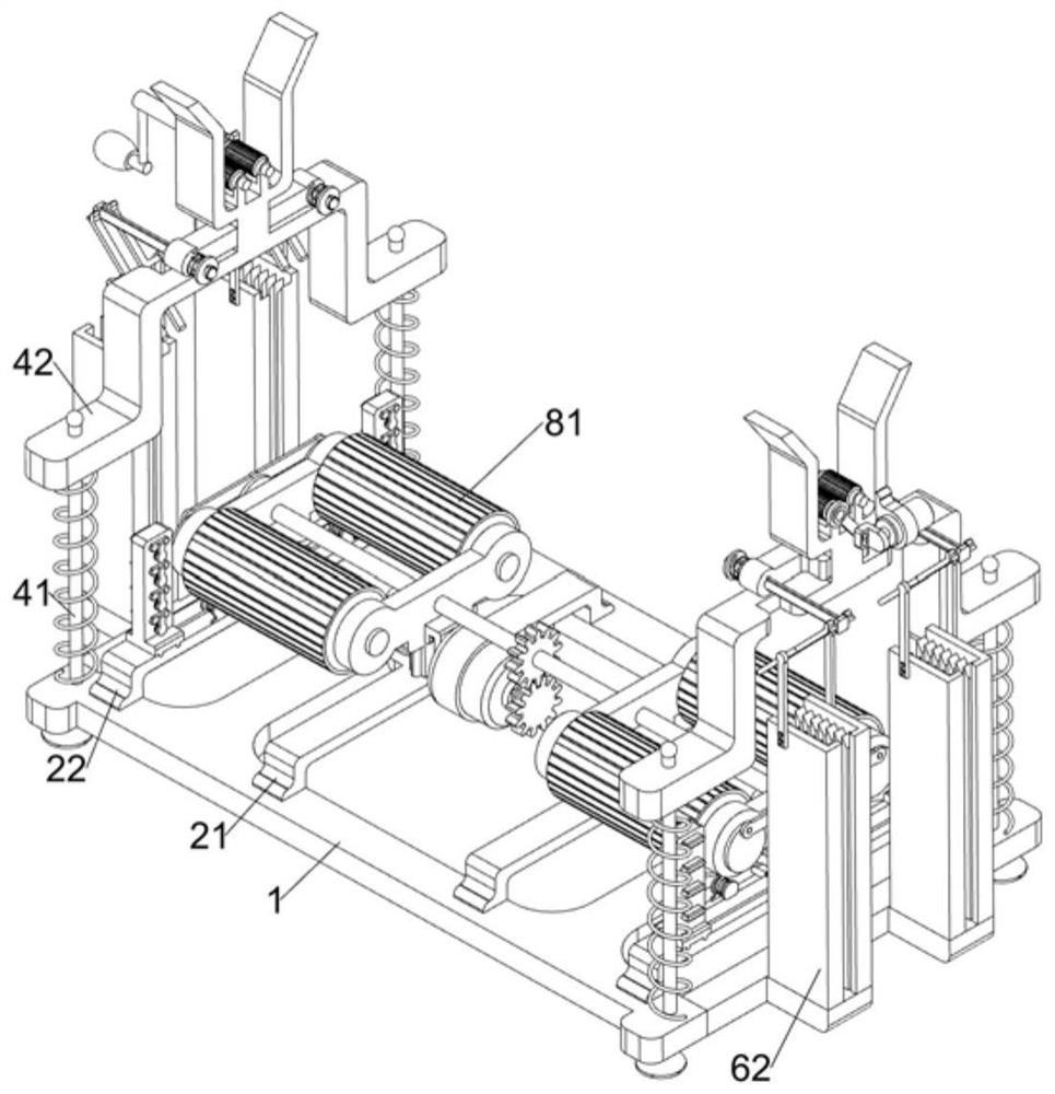
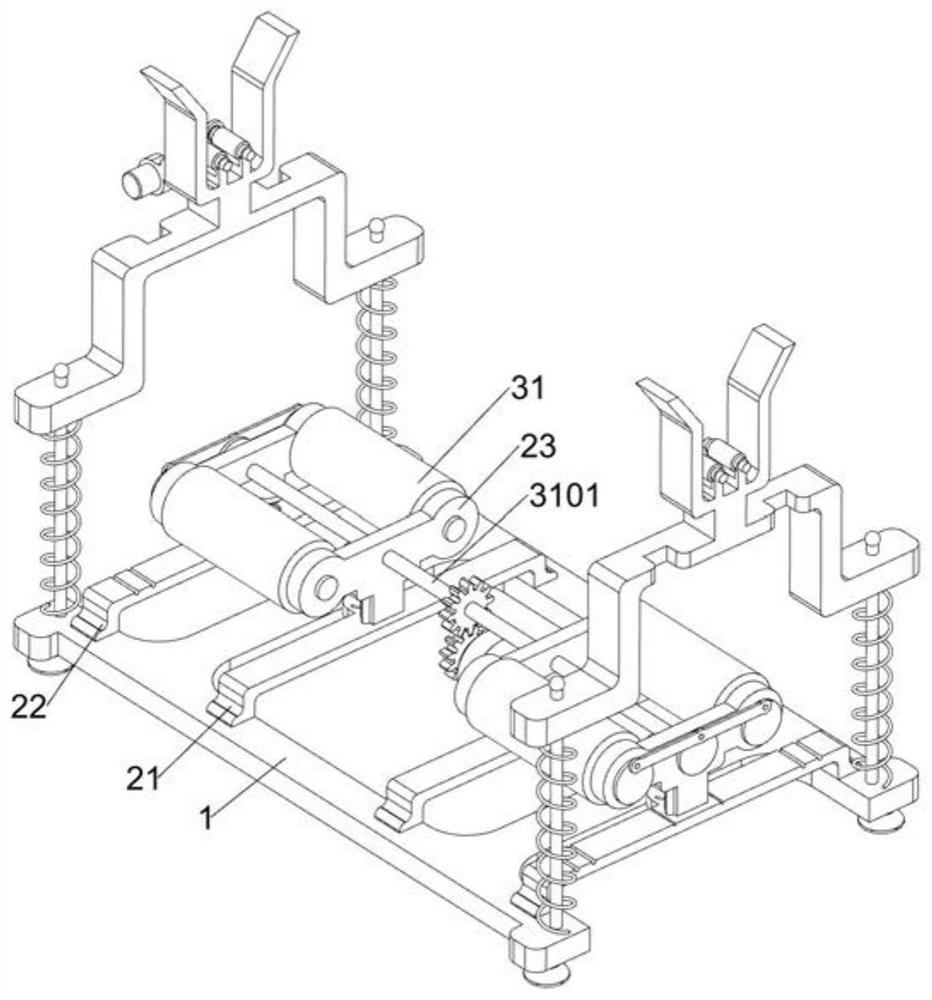
[0047] Actinomyces dual horizontal dual drive means, such as figure 1 , figure 2 , image 3 , Figure 4 , Figure 5 and Image 6 Shown, it comprises a bottom support frame 1, C-shaped support 21, C-shaped slot plate 22, a T-shaped slide plate 23, stretching spring 24, drive assembly 3 and the chassis assembly drive shaft 4, a top solid bottom bracket connected to a pair of C-shaped support 21, fixed to the top of the bottom bracket 1, a pair of C-shaped slot plate 22, the support frame C-shaped slot 22 and the C-shaped plate 21 above the middle are slidably connected to the slide plate 23 is T-shaped, T-shaped slide plate 23 is connected between each adjacent C-shaped support plate 21 and the C-shaped slot 22 and the telescopic spring 24, the slide 3 is provided with chassis drive assembly 23 on the T-plate, tray drive assembly 3 with rotation of the drive cable tray, the bottom of the support frame 4, the drive shaft 4 for driving the cable drum assembly rack drive assembly is provid...

Embodiment 2

[0052] On the basis of Example 1, such as Figure 7 , Figure 8 and Figure 9 Shown, further comprising a support assembly 5 adaptable adaptive support assembly 5 is provided on the C-shaped slot plate 22, the support assembly 5 can be adaptive so that the apparatus is suitable for different diameters of cable tray, supporting assembly 5 adaptability comprising a wedge pressing plate 51, the connecting plate 52, the tension spring 521, the slide frame 53 T-shaped, L-shaped slide plate 54 and a return spring 55, above the C-shaped slot plate 22 slidably connected to a pair of wedge-shaped pressing plate 51 , the pressing plate 51 is provided with an upper inclined surface of the wedge, the wedge pressing the contact plate 51 and the slide plate 23 adjacent to the T-shape, the two wedge-shaped pressing the ipsilateral side of the lower plate 51 away from each other are connected by welding connection plate 52, the connection plate 52 connected to the C-shaped slotted plate 22 between t...

Embodiment 3

[0055] On the basis of Example 2, such as Figure 10 , Figure 11 and Figure 12 Shown, comprises a further anti-slip assembly 6, the anti-slip assembly 6 is provided at the bottom of the support frame 1, the anti-slip assembly 6 for preventing the slide chassis around the cable when the cable is pulled other devices, anti-slip assembly 6 such that the device may application of different widths cable tray, anti-slip assembly 6 comprises a profiled support block 61, the stopper strip 62 is fixed to the expansion frame 63, L-shaped bracket aperture 64, the slide card struts 65, springs 66 and the universal homing ball 67, the bottom of the support frame 1 is connected symmetrically shaped support block 61, a top profiled supporting block 61 fixedly connected with two pairs of stopper strip 62 by welding, on the same side of the stopper strip 62 is opened close to each other a plurality of vertical chutes, the upper stopper strip 62 is connected to the expansion frame 63 is fixed, the s...


PUM


Abstract

The invention relates to the field of cable laying, in particular to a dual-drive horizontal dual-purpose pay-off device which comprises a bottom supporting frame, a C-shaped supporting frame, a C-shaped slotted plate, a sliding T-shaped plate and the like. The top of the bottom supporting frame is fixedly connected with a pair of C-shaped supporting frames, the top of the bottom supporting frame is fixedly connected with a pair of C-shaped slotting plates, and sliding T-shaped plates are slidably connected to the middles of the upper portions of the C-shaped slotting plates and the C-shaped supporting frames. The rotating roller drives the cable reel rack to rotate clockwise through friction force, so that the cable reel rack releases a cable, and the rotating supporting roller assists in driving the cable reel rack to rotate clockwise through friction force, so that dual drive can be provided, and the problem that the rotating roller cannot rotate to drive the cable reel rack to rotate when a disc on the cable reel rack has defects is solved; the limiting supporting frame and devices on the limiting supporting frame are supported by sliding the L-shaped plate, so that the limiting supporting frame can better support a shaft on a cable reel rack, a better supporting effect can be guaranteed, the pay-off process is safer, and the damage rate of a cable is reduced.

Description

Technical field [0001] The present invention relates to cabling, and in particular relates to dual-drive dual horizontal pay-off apparatus. Background technique [0002] Cables are made of one or more mutually insulated conductors and an outer insulation layer, the electric power for transmission of information from or to one another at the wire cable into the power cables, control cables, compensation cable, etc. they are made of single or multi-strand wire and an insulating layer, for connecting the circuits, and other electrical appliances, the cable plays an important role in the transmission of electrical energy. [0003] When laying the cables, the cable of the cable reel holder needs the discharge line, during the pulling laying, cable line current cabling apparatus substantially semi-automated format, can not be applied differently sized cable tray, the cable tray when the when the dimensional change, need to manually replace the tray, resulting in reduced efficiency of t...

Claims


Application Information

Patent Timeline
Patent Type & Authority Applications(China)
IPC IPC(8): B65H49/24B65H49/32B65H51/08H02G1/06
CPCB65H49/24B65H49/32B65H49/324B65H51/08H02G1/06B65H2701/34
Inventor 赵晓忠李强刘培强
Owner 无锡广盈集团有限公司
Why Eureka
Try Eureka